
A3 Mk2
| Removing and installing sump with balance shaft assembly and oil pump, engine code AXW, BLX, BHD, BLY, BLR, BMB |
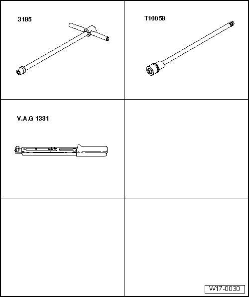
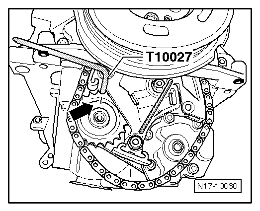
| Special tools and workshop equipment required |
| t | T-bar and socket, 10 mm -3185- |
| t | Allen key, long reach -T10058- |
| t | Torque wrench -V.A.G 1331- |
| t | Flat scraper |
 Note
Note
|
|
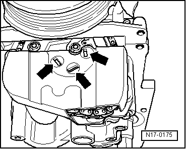
|
|
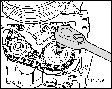
|
|
|
|
|
Note
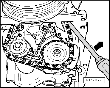
|
|
Note
|
|
|
|
Note
|
|
|
|
Note
|
|
Note
|
|
| Component | Nm | |
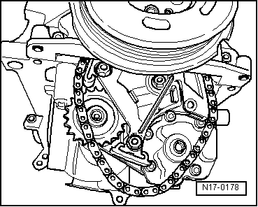
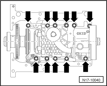
| Balance shaft assembly | 15 + 90° 1)2) | |
| Chain sprocket to oil pump | 20 + 90° 1)2) | |
| Oil pipe to balance shaft assembly | 10 | |
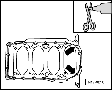
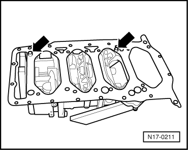
| Sump to cylinder block | 15 | |
| Sump to gearbox | 45 | |
| Oil drain plug | 30 | |
|