audi Workshop Repair Guides

Audi Workshop Service and Repair Manuals

Toothed belt drive - exploded view (vehicles with separate toothed belt covers) > < Toothed belt drive - exploded view (vehicles without separate toothed belt covers)
Removing and installing toothed belt (vehicles without separate toothed belt covers)
  Note
Vehicles from 01/2006 onwards are fitted with a new type of toothed belt cover. Identification: the top section of the toothed belt cover has no cap → Item and the toothed belt cover is divided near the engine support. Removing and installing toothed belt (vehicles with separate toothed belt covers) → Chapter.
Special tools and workshop equipment required
   
t  Support bracket -10 - 222 A-
  W00-0225
t  Shackle -10 - 222 A /12-
  W00-1091
t  Pin wrench -T10020-
  W00-0618
t  Locking pin -T10060A-
Removing
–  Detach engine cover panel with air cleaner → Rep. gr.24.
  WARNING
Hot steam or hot coolant can escape when expansion tank is opened; cover filler cap with cloth and open carefully.
–  Open filler cap on coolant expansion tank.
–  Remove noise insulation → Rep. gr.50.
  W00-10235
–  Remove noise insulation (right-side) -fasteners 1 ... 3-.
  A10-1643
–  Unscrew bolts -1 ... 3- and remove pendulum support.
  A10-1578
–  Unscrew bolts -arrows- and remove charge air pipe together with hoses.
–  Drain off coolant → Chapter
  WARNING
Fuel supply line is pressurised. Wear safety goggles and protective clothing to avoid possible injury and skin contact. Before removing from hose connection wrap a cloth around the connection. Then release pressure by carefully pulling hose off connection.
  A21-10030
–  Mark fuel line -1- and line going to ACF -2-.
–  Disconnect fuel line -1-.
–  Disconnect ACF line -2-.
–  Disconnect ACF line going to tank -3-.
–  Lift out ACF in -direction of arrow-.
  A21-10033
–  Detach the coolant hose at the bracket -1-.
–  Remove bracket for activated charcoal filter -arrows-.
  A21-10040
–  Unbolt filler neck for windscreen washer reservoir -1-.
–  Remove retaining clip; to do so, unscrew bolts -2 and 3-.
  A21-10034
–  Unplug electrical connector -1- from coolant level indicator.
–  Detach coolant expansion tank -arrows-.
  A21-10035
–  Disconnect coolant pipe -arrow-.
–  Remove poly-V belt and remove locking pin -T10060A- → Chapter.
  A21-10036
–  Position support bracket -10 - 222 A- on bolted flanges of wing panels. The spindles face forwards.
–  Attach hooks of spindles with shackles -10 - 222 A /12- to the lifting eyes.
  N15-10091
–  Remove securing bolts from assembly mounting/engine support -arrows- and remove complete assembly mounting.
  Caution
When raising engine with support bracket -10-222A-, ensure that components/hoses are not damaged, strained or torn off.
  N10-0437
–  Raise engine with support bracket -10-222A- until it is possible to loosen and remove the two top bolts -1 and 2- securing the engine support.
  N15-10144
–  Set camshaft sprocket to TDC marking by turning crankshaft. Marking on camshaft sprocket must align with arrow on toothed belt cover.
  N15-10145
–  Remove vibration damper / pulley.
  N15-10315
–  Unscrew bolts from toothed belt cover (bottom) -arrows-.
  N15-10075
–  Loosen bottom bolt -3- and remove engine support from below.
  N15-10144
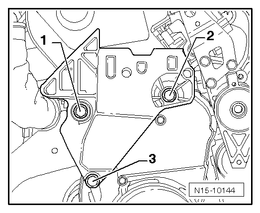
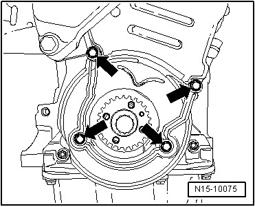
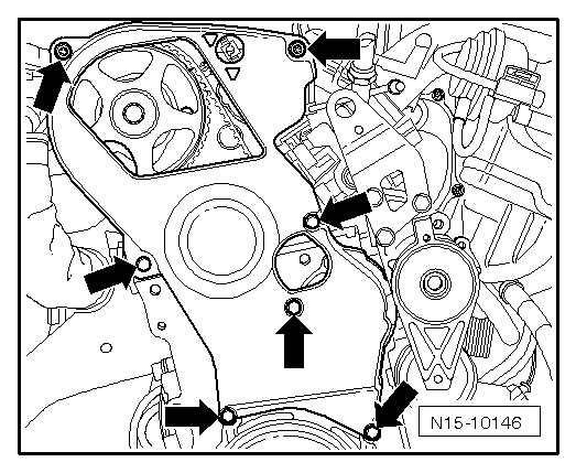
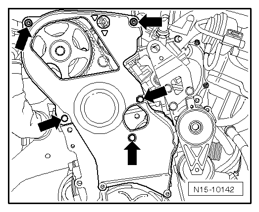
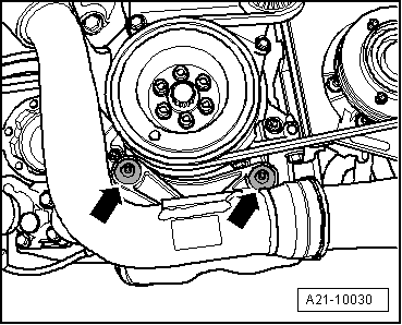
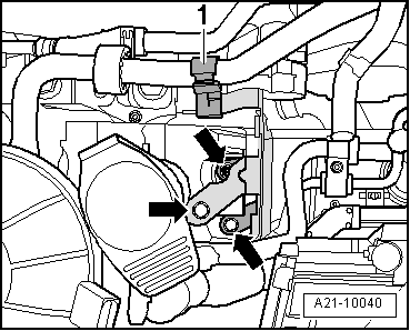
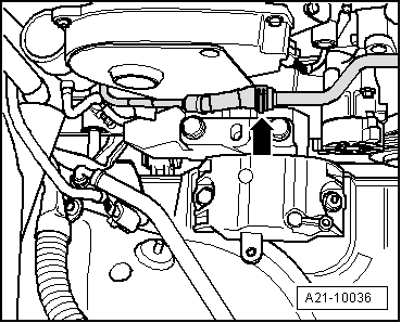
–  Unscrew remaining toothed belt cover bolts -arrows- and remove toothed belt cover from engine.
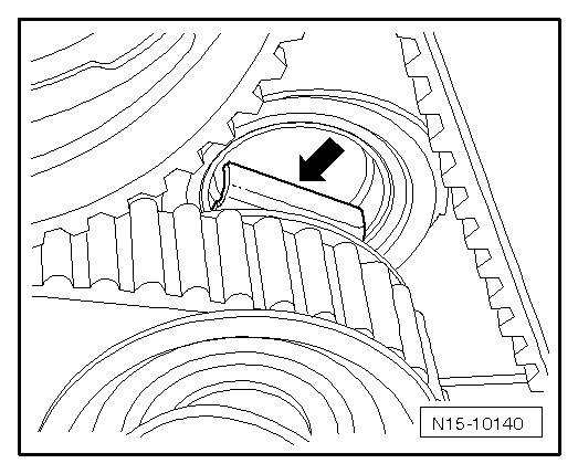
–  Mark direction of rotation of toothed belt.
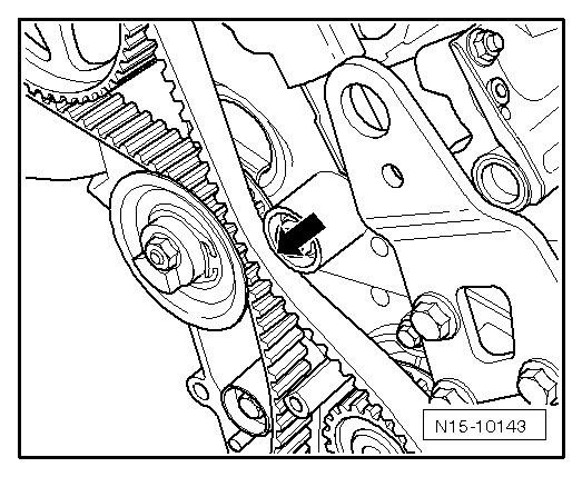
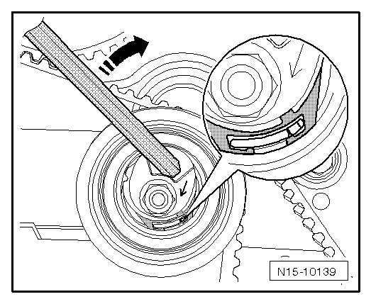
–  Loosen tensioning roller and remove toothed belt.
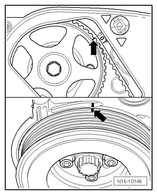
–  Turn crankshaft back slightly.
Installing
l  Tightening torques → Chapter
  Note
t  When turning the camshaft, the crankshaft must not be at TDC. Otherwise, there is a risk of damage to valves and piston crowns.
t  The engine must be no more than warm to touch.
–  Fit toothed belt on crankshaft sprocket (note rotation direction).
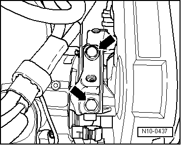
–  Secure toothed belt cover (bottom section) with the two bolts at the bottom.
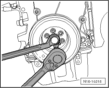
–  Install vibration damper / pulley with new bolts.
  N15-10142
–  Turn crankshaft and camshaft to TDC No. 1 cylinder -arrows-.
  N15-10145
–  Fit toothed belt in the sequence: tensioning roller, camshaft sprocket, coolant pump and last onto idler roller -arrow-.
  Note
  N15-10143
Check tensioning roller is seated correctly in cylinder head.
  N15-10140
–  Tension toothed belt. To do so, turn hexagon key at the eccentric adjuster clockwise (direction of arrow) until the notch is above the indicator.
–  Then release tension on toothed belt.
–  Now tension toothed belt until the notch and the indicator are aligned.
–  Tighten securing nut
–  Turn crankshaft two turns in direction of engine rotation and set again to TDC. Make sure that the engine is rotated without stopping during the final 45° (1/8 turn).
–  Check tension of toothed belt again. Specification: indicator and notch must align.
  N15-10139
–  Check valve timing again.
If the markings do not align:
–  Repeat adjustment of valve timing.
If the markings align:
  N15-10145
–  Install toothed belt cover -arrows-.
  Note
  N15-10146
Note different bolt lengths. Bolt -3- is approx. 25 mm shorter than bolts -1 and 2-.
  N15-10144
–  Insert bottom securing bolt -3- in engine support.
–  Install engine support on cylinder block from below and tighten bolt finger-tight.
–  Raise engine with support bracket -10-222A- until it is possible to screw in the two top bolts -1 and 2-.
–  Tighten all bolts.
–  Lower the engine down to installation position.
  N15-10144
–  Secure assembly mounting for engine to engine support -arrows-; to do so, bring surfaces into contact using support bracket -10-222A-.
–  Remove support bracket -10-222A-.
–  Attach fuel hoses onto connections. Make sure plug-in connectors are properly secured.
–  Install coolant expansion tank.
–  Connect battery → Electrical System; Rep. gr.27
–  Fit engine cover panel.
–  Install crankshaft pulley → Chapter.
–  Adjust engine mountings → Chapter.
–  Install poly V-belt → Chapter.
–  Install air pipes with plug-in connectors → Chapter.
–  Bleed fuel system → Motronic direct injection and ignition system (4-cylinder); Rep. Gr. 24; Servicing fuel injection system.
–  Install insulation tray.
  N10-0437

Toothed belt drive - exploded view (vehicles with separate toothed belt covers) > < Toothed belt drive - exploded view (vehicles without separate toothed belt covers)