| –
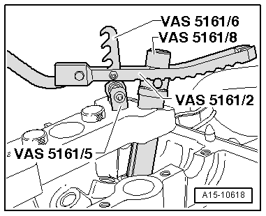
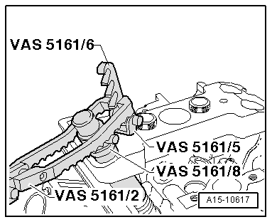
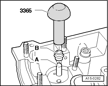
| Engage pressure fork -VAS 5161/2- at snap-in device, as shown in illustration. |
| Continuation for both sides: |
| –
| Press down with pressure fork for assembly cartridge. |
| –
| At the same time, turn knurled screw of assembly cartridge clockwise until tips engage in valve cotters. |
| –
| Turn knurled screw in both directions. |
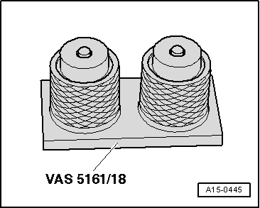
| l
| The valve cotters are forced apart and are taken up by the cartridge. |
| –
| Take out assembly cartridge. |
| –
| Detach guide plate and turn to one side. |
| –
| Detach valve spring with valve spring plate. |
|
|
|
 Caution