
A3 Mk2
|
|
|
|
|
 Note
Note
|
|
Note
|
|
Note
|
|
|
|
|
|
|
|
Note
|
|
|
|
|
|
|
|
|
|
|
|
 Caution
Note
|
|
|
|
|
|
Note
|
|
|
|
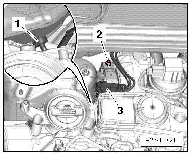
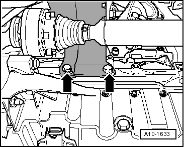
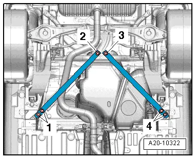
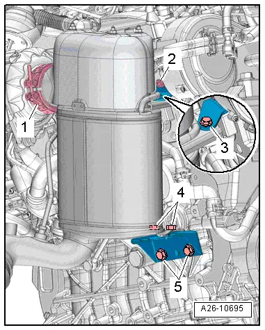
| 1. | Fit particulate filter to turbocharger, attach clip -1- without tightening | |||
| 2. | Fit bolts -2 ... 5- by hand without tightening
| |||
| 3. | Tighten clamp -1- | |||
| 4. | Tighten bolts -2- and -5-. | |||
| 5. | Tighten bolts -3- and -4-. | |||
|