
A3 Mk2
| Connection diagram for coolant hoses - engine code CBEA |
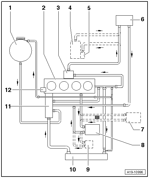
| 1 - | Coolant expansion tank |
| q | With filler cap |
| q | Checking pressure relief valve in filler cap → Anchor |
| 2 - | Cylinder head and cylinder block |
| q | If renewed, refill system with fresh coolant |
| 3 - | Exhaust gas recirculation cooler |
| q | If renewed, refill system with fresh coolant |
| q | Removing and installing → Chapter |
| 4 - | Auxiliary heater |
| 5 - | Circulation pump -V55- |
| 6 - | Heat exchanger for heater |
| q | If renewed, refill system with fresh coolant |
| 7 - | Gear oil cooler |
| q | For dual-clutch gearbox |
| q | If renewed, refill system with fresh coolant |
| 8 - | Engine oil cooler |
| 9 - | Engine preheating element -Z97- |
| q | Removing and installing → Chapter |
| 10 - | Radiator |
| q | If renewed, refill system with fresh coolant |
| 11 - | 4/2-way valve |
| q | Removing and installing → Chapter |
| 12 - | Coolant pump |
| Parts of cooling system - intake side |
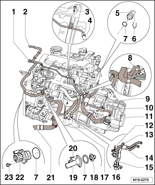
| 1 - | Coolant hose to coolant expansion tank (bottom) |
| 2 - | Coolant hose to coolant expansion tank (top) |
| 3 - | Bolt |
| q | 10 Nm |
| 4 - | Breather pipe |
| 5 - | Coolant temperature sender -G62- |
| 6 - | Retaining clip |
| 7 - | O-ring |
| q | Renew |
| 8 - | Gear oil cooler |
| q | Only on vehicles with dual clutch gearbox |
| 9 - | Coolant hose (supply) on engine oil cooler |
| q | On vehicles without gear oil cooler |
| q | On vehicles with gear oil cooler: coolant hose (return) on gear oil cooler |
| 10 - | Coolant hose (return) on engine oil cooler |
| 11 - | To top of radiator |
| 12 - | Bracket for wiring harness and coolant pipe |
| 13 - | Coolant hose |
| q | To coolant pipe at cylinder block |
| 14 - | Coolant hoses |
| q | For gear oil cooler |
| q | Only on vehicles with dual clutch gearbox |
| q | Installed according to vehicle equipment |
| 15 - | Coolant pipe |
| q | For engine pre-heating element -Z97- |
| q | Exploded view → Anchor |
| q | Installed according to vehicle equipment |
| 16 - | Engine preheating element -Z97- |
| q | Exploded view → Anchor |
| q | Removing and installing → Chapter |
| q | Installed according to vehicle equipment |
| 17 - | Engine oil cooler |
| 18 - | Thermostat |
| q | Checking thermostat → Chapter |
| 19 - | Connection |
| 20 - | Bolt |
| q | 15 Nm |
| 21 - | Hose to bottom of radiator |
| 22 - | Coolant pump |
| 23 - | Bolt |
| q | 40 Nm |
| Engine preheating element -Z97- - exploded view |
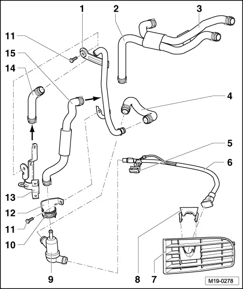
| 1 - | Coolant pipe for engine preheating element -Z97- |
| 2 - | Coolant hose between connection on cylinder block and gear oil cooler |
| 3 - | Coolant hose between gear oil cooler and engine oil cooler |
| 4 - | Coolant hose between coolant pipe for engine preheating and engine preheating element -Z97- |
| 5 - | Locking device |
| 6 - | Cable for connection to external current source |
| 7 - | Air intake grille (left-side) |
| – | Removing and installing air intake grille → Rep. gr.63 |
| 8 - | Bracket |
| 9 - | Engine preheating element -Z97- |
| q | Removing and installing → Chapter |
| 10 - | Clamp for engine preheating element -Z97- |
| q | Secured to bracket |
| 11 - | Bolt |
| q | 10 Nm |
| 12 - | Bracket for engine preheating element -Z97- |
| 13 - | Bracket for wiring harness and coolant pipe |
| 14 - | Coolant hose between engine oil cooler and coolant pipe for engine preheating element -Z97- |
| 15 - | Coolant hose between engine preheating element -Z97- and coolant pipe on cylinder block |
| Parts of cooling system - gearbox side |
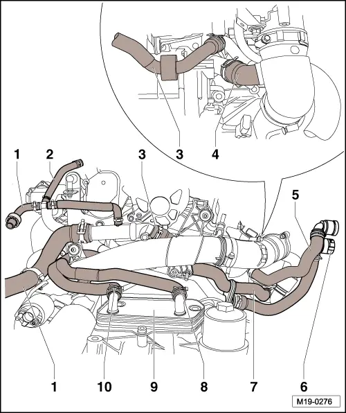
| 1 - | Coolant hose (supply) on radiator |
| 2 - | Coolant hose to breather pipe |
| 3 - | Coolant hose (return) to exhaust gas recirculation cooler |
| 4 - | Coolant hose (return) on radiator |
| 5 - | Coolant hose (supply) on heat exchanger |
| 6 - | Coolant hose (return) on heat exchanger |
| 7 - | Coolant hose (supply) on exhaust gas recirculation cooler |
| 8 - | Coolant hose (supply) on gear oil cooler |
| 9 - | Gear oil cooler |
| 10 - | Coolant hose (return) on gear oil cooler |