audi Workshop Repair Guides

Audi Workshop Service and Repair Manuals

Pistons and conrods > < Extracting and driving in needle bearing for crankshaft
Pulling spur gear off crankshaft and shrink-fitting new spur gear
   
t  Fitting tool -10 - 203-
  W00-0258
t  Puller -T10392-
t  Temperature gauge -VAS 6519-
  W00-10696
t  Hotplate (commercially available)
t  Protective gloves
Procedure
–  Remove sealing flange (pulley end) → Chapter.
–  Remove sump → Chapter.
  Note
t  If the balance shaft assembly does not have to be renewed, it is sufficient just to remove the idler gear.
t  If the bolt for the idler gear for the balance shaft assembly has been slackened or the spur gear on the crankshaft or the crankshaft itself have been renewed, you must install a new idler gear with the appropriate coating. Procedure for installation → Chapter „Installing a new balance shaft assembly“.
–  Remove idler gear → Item for balance shaft assembly or remove balance shaft assembly → Chapter.
  N17-10172
–  Insert thrust piece -T10392/1- in end of crankshaft.
  A17-10455
–  Insert puller -T10392- in holes in spur gear, turn clockwise -arrow- and screw in locking pins -A-.
  A17-10453
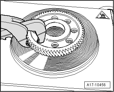
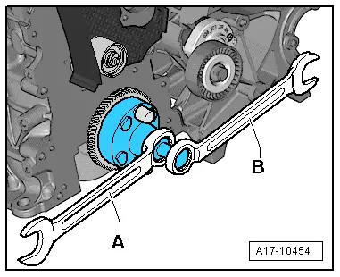
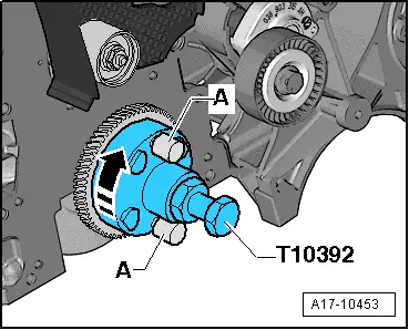
–  Counterhold crankshaft with ring spanner -A- and pull spur gear off end of crankshaft by screwing in spindle with ring spanner -B-.
  Note
t  
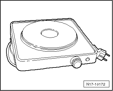
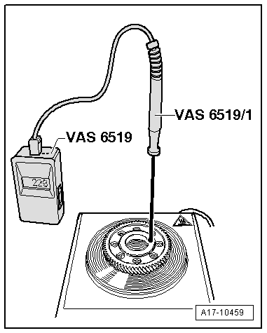
While heating up the new spur gear, monitor the temperature with the temperature gauge -VAS 6519-.
t  When the temperature reaches 200 °C, you have approx. 4 seconds to fit the spur gear on the crankshaft.
t  A higher temperature increases the amount of time available (220 °C = approx. 6 seconds).
t  
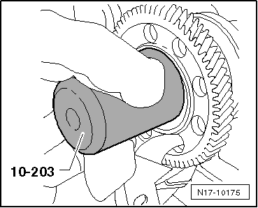
Make sure the end of the crankshaft is clean.
  Caution
Do not exceed a maximum temperature of 240 °C; otherwise the spur gear can become discoloured and distorted.
  A17-10454
–  Place the new spur gear flat on a hotplate (commercially available) and heat it to at least 200 °C, but not more than 240 °C. The lettering must face upwards.
–  Set temperature gauge -VAS 6519- to measuring range 2.
–  Position temperature sensor -VAS 6519/1- on collar of spur gear (as shown) and read off temperature at temperature gauge.
  WARNING
Risk of burns. Use suitable protective gloves for the following steps.
  A17-10459
–  When the required temperature has been reached, pick up the spur gear with pliers as illustrated.
  Note
Take care not to damage the teeth of the spur gear.
  A17-10456
–  With the aid of fitting tool -10 - 203-, slide spur gear by hand onto end of crankshaft as far as stop. This must be done without delay, taking care to keep the gear straight.
–  Wait a few minutes to allow the spur gear to cool down.
–  Install balance shaft assembly → Chapter „Installing a new balance shaft assembly“.
or
–  Install idler gear for balance shaft assembly → Chapter „Installing a new balance shaft assembly“.
–  Install sealing flange (pulley end) → Chapter.
  N17-10175

Pistons and conrods > < Extracting and driving in needle bearing for crankshaft