
A3 Mk2
 Note
Note
|
|
|
|
|
Note
|
|
|
|
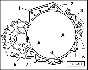
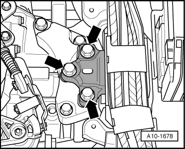
| Item | Bolt | Nm | ||||
| 1, 2 | M12x55 1)2) | 80 | ||||
| 3, 4 | M12x165 1) | 80 | ||||
| 5 | M12x105 2) | 80 | ||||
| 6, 7 | M10x50 2) | 40 | ||||
| 8 | M10x70 2) | 40 | ||||
| A | Dowel sleeves for centralising | |||||
| ||||||
|
|
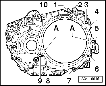
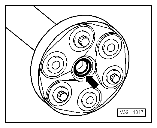
| Item | Bolt | Nm | ||
| 1, 3, 10 | M12x55 | 80 | ||
| 5, 9 | M12x70 | 80 | ||
| 6, 7, 8 | M10x50 | 40 | ||
| A | Dowel sleeves for centralising | |||
| ||||
|
|
Note
|
|
|
|
 Caution
|
|
Note
|
|
| Component | Nm | ||
| Bolts/nuts | M6 | 10 | |
| M7 | 15 | ||
| M8 | 20 | ||
| M10 | 40 | ||
| M12 | 65 | ||
| Except for the following: | |||
| Starter to dual-clutch gearbox | 40 | ||
| Underbody cross member to body | 23 | ||
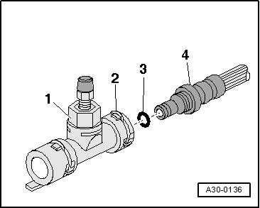
| Charge pressure solenoid valve -N75- to bracket | 8 | ||
| Terminal B+ to starter | 16 | ||
| Earth cable | 22 | ||
| Oil pressure switch to oil filter bracket | 20 | ||
| Air pipe (left-side) to bracket | 8 | ||
| Air cleaner housing to bracket | 10 | ||
| Air pipe (right-side) to bracket | 8 | ||
| Heat shield to cylinder block | 35 | ||