audi Workshop Repair Guides

Audi Workshop Service and Repair Manuals

Radiator and radiator fans - exploded view > < Checking thermostat
Removing and installing coolant pipe
Special tools and workshop equipment required
   
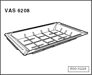
t  Drip tray for workshop hoist -VAS 6208-
  W00-10228
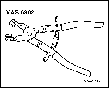
t  Hose clip pliers -VAS 6362-
  W00-10427
Removing
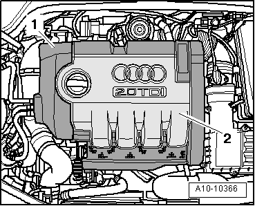
–  Lift off engine cover panel (outside -1- and inside -2-) by pulling up evenly.
  A10-10366
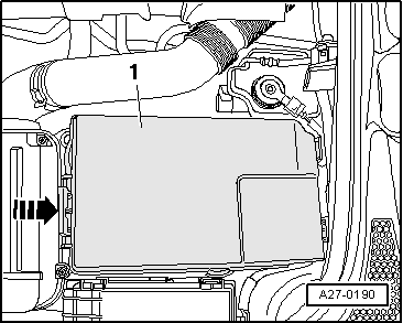
–  Remove cover -1- over battery; to do so, press release tab -arrow-.
  A27-0190
  Caution
Observe notes on procedure for disconnecting the battery → Rep. gr.27.
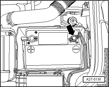
–  With ignition switched off, disconnect battery earth cable -arrow-.
  WARNING
Hot steam or hot coolant can escape when expansion tank is opened; cover filler cap with cloth and open carefully.
–  Open filler cap on coolant expansion tank.
  A27-0191
–  Remove front right wheel.
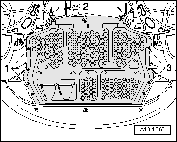
–  Remove centre noise insulation -fasteners 1 ... 3-.
  A10-1565
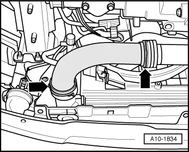
–  Remove air intake hose (left-side) by lifting retaining clips -arrows- slightly.
  A10-1834
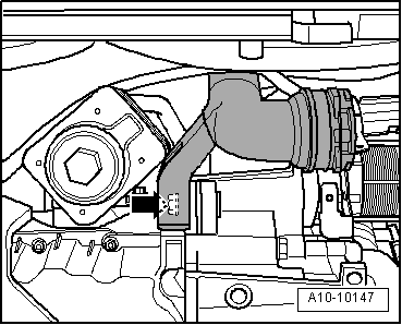
–  Remove bolt -arrow- for air intake pipe (left-side).
  A10-10147
–  Place drip tray for workshop hoist -VAS 6208- under engine.
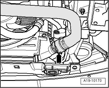
–  Lift retaining clip -arrow- and disconnect coolant hose from radiator.
  A19-10170
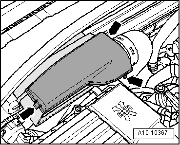
–  Pull cover off air duct (release clips on sides) -arrows-.
  A10-10367
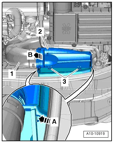
–  Release clips on left and right -arrow A- and unclip air duct at bottom -2-.
–  Swivel air duct (bottom) slightly to the rear and detach air duct (bottom) from retainers -3-.
–  Detach air pipe -1- from air duct (bottom) -arrow B-.
  A10-10919
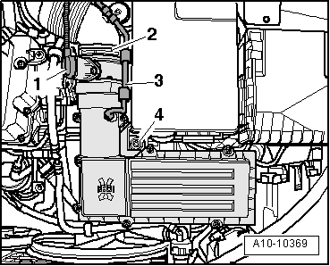
–  Unplug electrical connector -1- at air mass meter -G70-.
–  Detach vent hose -3- and air hose -2-.
–  Unscrew bolt -4- and remove air cleaner housing.
  A10-10369
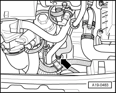
–  Place drip tray for workshop hoist -VAS 6208- under engine.
–  Disconnect coolant hose at bottom of engine oil cooler -arrow- and drain off coolant.
  A19-0483
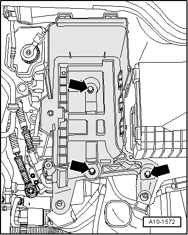
–  Remove battery → Rep. gr.27.
–  Remove battery tray -arrows-.
  A10-1572
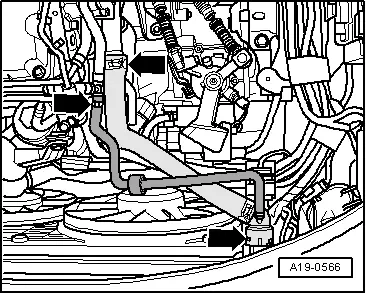
–  Remove coolant hose between engine and radiator -arrows-.
  A19-0566
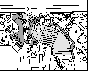
–  Detach crankcase breather hose -2-.
–  Move vent hose -4- and vacuum hoses -1- clear at air intake hose.
–  Remove bolt -3-.
–  Swing air hose to rear and detach from turbocharger.
  A10-10370
Vehicles with manual gearbox:
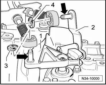
–  Detach securing clip -3- for gear selector cable from gearbox selector lever -1- and pull cable off pin -arrow-.
Metal gate relay lever:
–  Detach securing clip -4- for gate selector cable from gate relay lever -2- and pull cable off pin -arrow-.
  N34-10000
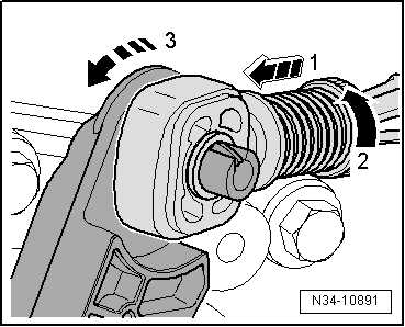
Plastic gate relay lever:
l  To prevent damage to gate selector cable, cable end-piece must be detached from gate selector cable before removing.
–  Pull locking device forwards onto stop -arrow 1- and lock by turning anti-clockwise -arrow 2-.
–  Press gate relay lever towards front -arrow 3-.
  N34-10891
Vehicles with manual gearbox (continued):
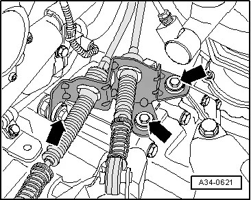
–  Remove selector cable support bracket -arrows- from gearbox and place to one side.
  A34-0621
All vehicles (continued):
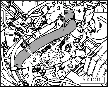
–  Remove bolts -arrows-.
–  Detach air pipe (left-side) from turbocharger by lifting retaining clips -arrows- slightly.
–  Remove air pipe from engine compartment downwards.
  A10-10211
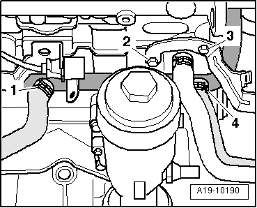
–  Set aside wiring harness in vicinity of coolant pipe.
–  Remove bolts -2- and -3-.
–  Detach coolant hoses -1- and -4-.
  A19-10190
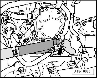
–  Detach coolant hose -arrow- at coolant hose/pipe connection.
  A19-10066
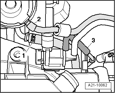
–  Detach oil supply hose -1- from turbocharger.
  Note
Disregard items marked -2- and -3-.
  A21-10062
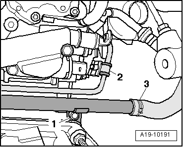
–  Remove bolt -1- for coolant pipe.
–  Disconnect coolant hose -3-.
–  Detach oil supply pipe at bracket -2-.
  A19-10191
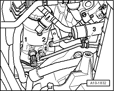
–  Unplug electrical connector at oil pressure switch -F1-.
–  Unscrew oil pressure switch -1-.
–  Detach oil supply pipe going to turbocharger at retaining clip -3- and at oil filter bracket -2-.
–  Detach oil supply pipe.
–  Detach coolant pipe.
Installing
Installation is carried out in the reverse order; note the following:
  Note
t  Renew gaskets, seals and O-rings.
t  Secure all hose connections with the correct type of hose clips (same as original equipment) → Electronic parts catalogue.
–  Clean and smoothen contact surface for seal.
  A10-1832
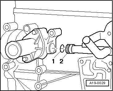
–  Lubricate new seal -1- with coolant additive and push onto coolant pipe -2-.
–  Push coolant pipe into bore on cylinder block.
Vehicles with manual gearbox
–  Attach and adjust selector mechanism at gearbox → Rep. gr.34.
All vehicles (continued):
–  Install air pipes/hoses with plug-in connectors → Chapter.
–  Install battery → Rep. gr.27.
–  Connect coolant hose to radiator → Fig..
–  Fill cooling system → Anchor.
Tightening torques
  A19-0029
ComponentNm
Coolant pipe to cylinder blockM715
M1040
Oil supply pipe to oil filter flange22
Retaining clip for oil supply pipe to:Coolant pipe10
Bracket10
Bracket for wiring harness15
Air duct (left-side) to bracket8
Air cleaner housing to bracket10


Radiator and radiator fans - exploded view > < Checking thermostat