
A3 Mk2
 Note
Note |
|
|

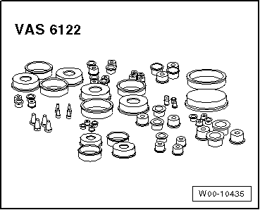
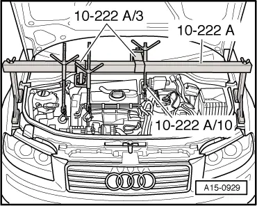
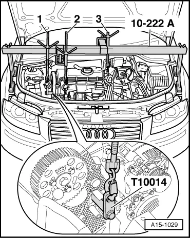
| Special tools and workshop equipment required |
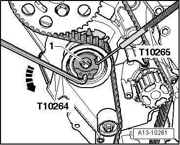
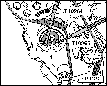
| t | Support bracket -10 - 222 A- |
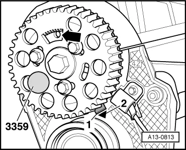
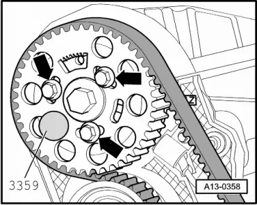
| t | Diesel injection pump locking pin -3359- |
| t | Drip tray for workshop hoist -VAS 6208- |
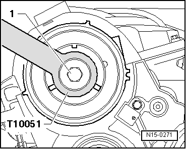
| t | Counterhold tool -T10051- |
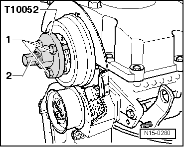
| t | Puller -T10052- |
|
|
|
|
|
|
|
|
|
|
|
|
|
|
 Caution
 WARNING
|
|
|
|
|
|
|
|
|
|
|
|
|
|
|
|
|
|
|
|
|
|
|
|
|
|
|
|
|
|
|
|
|
|
|
|
|
|
|
|
|
|
|
|
|
|
|
|
|
|
|
|
|
|
|
|
|
|
|
|
|
|
|
|
|
|
|
|
|
|
Note
|
|
|
|
|
|
|
|
|
|
|
|
Note
|
|
Note
|
|
Note
|
|
|
|
|
|
|
|
|
|
|
|
|
|
|
|
|
|
|
|
|
|