
A3 Mk2
| Pistons and conrods - exploded view |
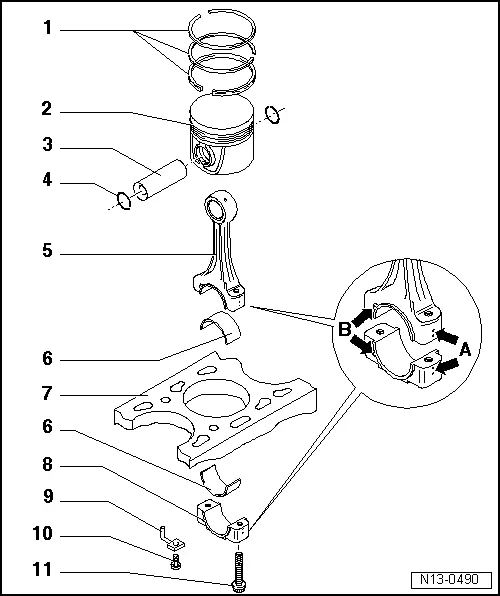
| 1 - | Piston rings |
| q | Offset gaps by 120° |
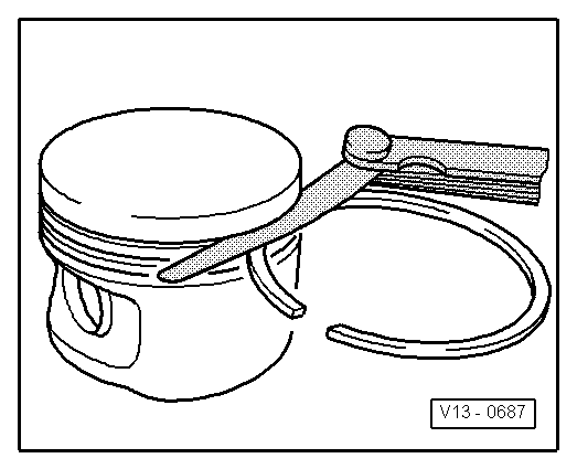
| q | Use piston ring pliers to remove and install |
| q | Marking „TOP“ or inscription must face piston crown. |
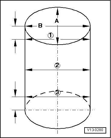
| q | Checking ring gap → Fig. |
| q | Checking ring-to-groove clearance → Fig. |
| 2 - | Piston |
| q | With combustion chamber |
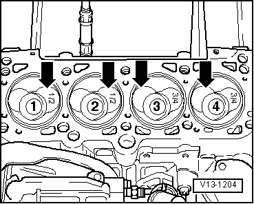
| q | Mark installation position and cylinder number |
| q | Installation position and allocation of piston/cylinder → Fig. |
| q | Arrow on piston crown points to pulley end |
| q | If cracking is visible on piston skirt, renew piston |
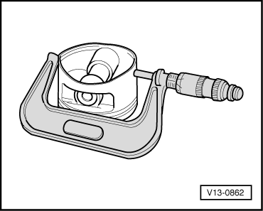
| q | Checking piston → Fig. |
| q | Piston and cylinder dimensions → Chapter |
| q | Checking cylinder bore → Fig. |
| q | Install using piston ring clamp |
| q | Measuring piston projection at TDC → Chapter |
| 3 - | Piston pin |
| q | If difficult to move, heat piston to approx. 60 °C |
| q | Remove and install using drift -VW 222 A- |
| 4 - | Circlip |
| q | Renew |
| 5 - | Conrod |
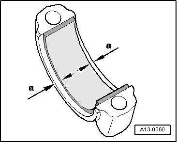
| q | Mark cylinder allocation -A- |
| q | Installation position: Marking -B- faces towards pulley end |
| q | With industrially cracked conrod bearing cap |
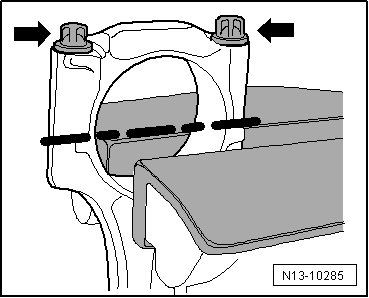
| q | Separating parts of new conrod → Fig. |
| q | Axial clearance: wear limit: 0.37 mm |
| q | Measuring radial clearance → Chapter |
| 6 - | Bearing shell |
| q | Installation position → Fig. |
| q | Mark used bearing shells for re-installation but not on bearing surface |
| q | Bearing shells worn down to the base layer must be renewed |
| q | Note type: upper bearing shell (closest to piston) is made of more wear-resistant material. Distinguishing feature on new bearing shells: black marking on bearing surface near joint |
| q | Check that it is securely seated |
| 7 - | Cylinder block |
| q | Checking cylinder bore → Fig. |
| q | Piston and cylinder dimensions → Chapter |
| 8 - | Conrod bearing cap |
| q | Note installation position |
| q | Since industrially cracked conrods are used (the conrod is cast as one unit and the cap is then cracked off), the conrod bearing cap can only be fitted in one position on the corresponding conrod |
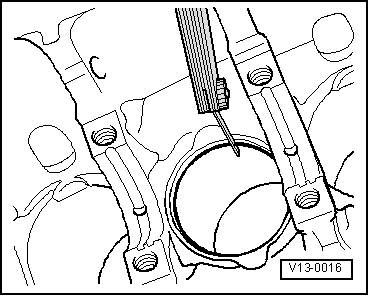
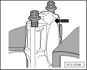
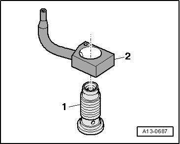
| 9 - | Oil spray jet |
| q | For piston cooling → Fig. |
| 10 - | 27 Nm |
| q | Insert without sealant |
| 11 - | Conrod bolt, 30 Nm + 90° further |
| q | Renew |
| q | Lubricate threads and contact surface |
|
|
| 1.9 ltr. engine | new mm | Wear limit mm |
| 1st compression ring | 0.30 … 0.40 | 1.00 |
| 2nd compression ring | 0.20 … 0.45 | 1.00 |
| Oil scraper ring | 0.25 … 0.55 | 1.00 |
| 2.0 ltr. engine | new mm | Wear limit mm |
| 1st compression ring | 0.30 … 0.40 | 1.00 |
| 2nd compression ring | 0.30 … 0.50 | 1.00 |
| Oil scraper ring | 0.25 … 0.50 | 1.00 |
|
|
| 1.9 ltr./2.0 ltr. engine | new mm | Wear limit mm |
| 1st compression ring | 0.06 … 0.09 | 0.25 |
| 2nd compression ring | 0.05 … 0.08 | 0.25 |
| Oil scraper ring | 0.03 … 0.06 | 0.15 |
|
|
|
|
|
|
|
|
|
|
 Note
Note
|
|