
A3 Mk2
|
|
|
|
|
|
|
 Note
Note
|
|
|
|
|
|
|
|
|
|
Note
|
|
|
|
Note
|
|
|
|
|
|
|
|
|
|
Note
|
|
| Component | Nm |
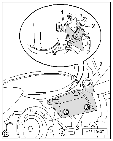
| Bracket for exhaust system to subframe | 23 |
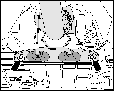
| Front exhaust pipe to turbocharger | 7 |
| Bracket for particulate filter to particulate filter | 23 |
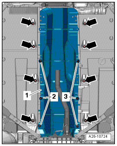
| Heat shield to cylinder block | 35 |
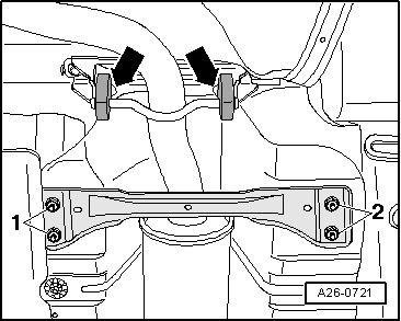
| Underbody cross member (front) to body | 23 |
| Pressure pipe to particulate filter | 40 |
| Air pipe (right-side) to bracket | 8 |