audi Workshop Repair Guides

Audi Workshop Service and Repair Manuals

Assembly mountings > < Securing engine to assembly stand
Installing engine
Installing engine
Procedure
l  Engine installed on engine bracket -T10012-.
Installation is carried out in the reverse order; note the following:
  Note
t  Renew self-locking nuts and bolts when performing assembly work.
t  Renew bolts which are tightened to a specified angle as well as oil seals and gaskets.
t  Secure all hose connections with the correct type of hose clips (same as original equipment) → Parts catalogue.
–  Clean input shaft splines and (in the case of used clutch plates) the hub splines. Remove corrosion and apply only a very thin coating of grease -G 000 100- to the splines. Then move clutch plate back and forth on input shaft until the hub moves smoothly on the shaft. Remove any excess grease.
–  Check whether dowel sleeves for centring the engine/gearbox assembly are fitted in the cylinder block; install if necessary.
   
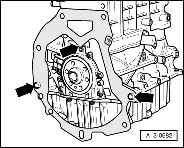
–  Ensure that the intermediate plate is engaged on the sealing flange and pushed onto the dowel sleeves -arrows-.
–  Check that clutch plate is correctly centred → Rep. Gr.30.
–  Check clutch release bearing for wear, renew if necessary.
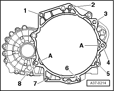
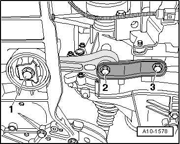
–  Bolt gearbox to engine.
  Note
t  Tightening torques apply only to lightly greased, oiled, phosphated or black-finished nuts and bolts.
t  Additional lubricants such as engine or gearbox oil may be used, but do not use lubricants containing graphite.
t  Do not use degreased parts.
t  Tolerance for tightening torques ± 15 %.
  A13-0682
Securing engine to gearbox
  A37-0214
ItemBoltNm
1, 2 1), 8 M12x5580
3 1), 4 1)M12x15080
5 … 7M10x5045
ADowel sleeves for centralising
l  1) Bolt with M8 stud

–  Guide engine/gearbox assembly into the body.
   
–  Tighten bolts of assembly mounting on engine -arrows- initially finger-tight.
  A10-1642
–  Tighten bolts of assembly mounting on gearbox -arrows- initially finger-tight.
–  Use new securing bolts.
  Note
The bolts are tightened to final torque only after adjusting the engine mountings → Chapter.
–  Remove engine bracket -T10012- from engine.
–  Install drive shafts → Rep. Gr.40.
  A10-1634
–  Secure pendulum support with bolts -1 ... 3- to gearbox and subframe.
–  Use new securing bolts.
–  Install exhaust system and align it free of stress → Chapter.
–  Install air conditioner compressor → Rep. Gr.87.
–  Install radiator → Chapter.
–  Install alternator → Rep. Gr.27.
–  Install poly V-belt → Chapter.
–  Install slave cylinder for hydraulic clutch mechanism → Rep. Gr.30.
  Caution
The clutch pedal must not be operated before installing slave cylinder.
–  Attach and adjust selector mechanism at gearbox → Rep. Gr.34.
–  Install air pipes/hoses with plug-in connectors → Chapter.
–  Adjust assembly mountings → Chapter.
–  Electrical connections and routing → Current flow diagrams, Electrical fault finding and Fitting locations.
–  Install battery → Rep. Gr.27.
  Caution
Do not use a battery charger to boost starting. There is danger of damaging the vehicle's control units.
–  Check oil level → Chapter.
–  Fill cooling system → Anchor.
  Note
t  Drained-off coolant may only be used again if the original cylinder head and cylinder block are re-installed.
t  Contaminated or dirty coolant must not be used again.
Tightening torques
  Note
t  Tightening torques apply only to lightly greased, oiled, phosphated or black-finished nuts and bolts.
t  Additional lubricant such as engine oil or gearbox oil may be used, but do not use lubricant containing graphite.
t  Do not use degreased parts.
t  Tolerance for tightening torques ± 15 %.
  A10-1578
ComponentNm
Bolts/nutsM610
 M715
 M820
 M1040
 M1265
Except for the following: 
Gearbox support to gearbox60 + 90° 1)2)
Air intake pipe (left-side) to sump10
Pendulum support to gearbox40 + 90° 1)2)
Pendulum support to subframe100 + 90° 1)2)
Terminal B+ to starter16
Earth wire to gearbox22
l  1) Renew bolts.
l  2) 90° = one quarter turn.


Assembly mountings > < Securing engine to assembly stand