
A3 Mk2
| Toothed belt drive - exploded view of components |

| 1 - | 10 Nm + 90° (1/4 turn) further |
| q | Renew |
| 2 - | Vibration damper |
| q | With pulley for poly V-belt |
| q | Removing and installing → Chapter |
| 3 - | Toothed belt cover (bottom) |
| 4 - | 10 Nm |
| q | Install using locking fluid; for locking fluid refer to → Parts catalogue |
| 5 - | Toothed belt cover (centre) |
| q | To remove, take out top toothed belt cover and unbolt poly V-belt tensioner |
| 6 - | Toothed belt cover (top) |
| q | To remove, take out air pipe (right-side) |
| q | Engage carefully in centre toothed belt cover when installing |
| 7 - | Toothed belt |
| q | Before removing, mark direction of rotation with chalk or felt-tipped pen. If the belt runs in the opposite direction when it is refitted, this can cause breakage. |
| q | Check for wear |
| Vehicles up to approx. 05.2005 |
| q | Removing → Chapter |
| q | Installing (adjusting valve timing) → Anchor |
| Vehicles from approx. 06.2005 |
| q | Removing → Chapter |
| q | Installing (adjusting valve timing) → Anchor |
| 8 - | 20 Nm + 45° (1/8 turn) further |
| 9 - | Tensioning roller |
| 10 - | 25 Nm |
| 11 - | Camshaft sprocket |
| q | Mark installation position |
| 12 - | 100 Nm |
| q | Use counterhold tool -T10051- when loosening and tightening → Chapter „Removing and installing camshaft“ |
| 13 - | Hub |
| q | With sender wheel for Hall sender -G40- |
| q | Use counterhold tool -T10051- when loosening and tightening |
| q | To remove, use puller -T10052- |
| q | Pulling off: Vehicles up to approx. 05.2005 → Anchor, vehicles from approx. 06.2005 → Anchor |
| 14 - | 10 Nm |
| q | Install using locking fluid; for locking fluid refer to → Parts catalogue |
| 15 - | Toothed belt cover (rear) |
| q | To remove, take out coolant pump → Chapter |
| q | When installing, engage carefully in sealing flange at pulley end. |
| 16 - | Rubber grommet |
| q | Renew if damaged |
| 17 - | 25 Nm |
| 18 - | O-ring |
| q | Renew |
| 19 - | Coolant pump |
| q | Removing and installing → Chapter |
| 20 - | 13 Nm |
| 21 - | Idler roller |
| 22 - | Crankshaft sprocket |
| q | Contact surface between sprocket and crankshaft must be free of oil |
| q | Can only be installed in one position |
| q | Removing and installing → Fig. |
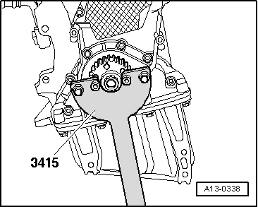
| 23 - | 120 Nm + 90° (1/4 turn) further |
| q | Renew |
| q | Do not lubricate with oil |
| q | Use counterhold tool -3415- when loosening and tightening → Fig. |
| 24 - | 22 Nm |
| 25 - | 10 Nm |
| q | Install using locking fluid; for locking fluid refer to → Parts catalogue |
|
|