
A3 Mk2
 Note
Note
|
|
|
Note
|
|
|
|
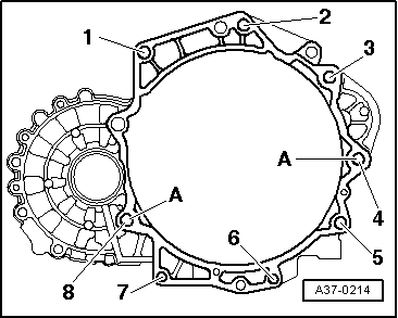
| Item | Bolt | Nm | ||
| 1 1), 2 1) | M12x55 | 80 | ||
| 3 , 4 | M12x165 | 80 | ||
| 5 1) | M12x105 | 80 | ||
| 6 1), 7 1) | M10x50 | 40 | ||
| 8 1) | M10x70 | 40 | ||
| A | Dowel sleeves for centralising | |||
| ||||
|
|
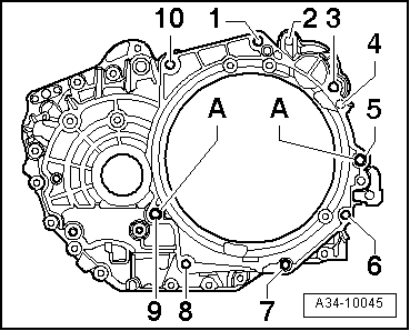
| Item | Bolt | Nm | ||
| 1 1), 3 1), 10 1) | M12x55 | 80 | ||
| 5 1), 9 1) | M12x70 | 80 | ||
| 6 … 8 1) | M10x50 | 40 | ||
| A | Dowel sleeves for centralising | |||
| ||||
|
|
|
Note
|
|
|
|
Note
|
|
 WARNING
| Component | Nm | ||||||
| Bolts/nuts | M6 | 10 | |||||
| M7 | 15 | ||||||
| M8 | 20 | ||||||
| M10 | 40 | ||||||
| M12 | 65 | ||||||
| Except for the following: | |||||||
| Direct shift gearbox: Starter to gearbox | 40 | ||||||
| Manual gearbox: Gearbox support to gearbox | 60 + 90° 1)2) | ||||||
| Pendulum support to: | Gearbox / subframe | Manual gearbox → Rep. Gr.34, automatic gearbox → Rep. Gr.37 | |||||
| Lock carrier to body | 10 | ||||||
| Terminal B+ to starter | 16 | ||||||
| Earth wire to gearbox | 22 | ||||||
| Air cleaner housing to bracket | 10 | ||||||
| Drive shaft heat shield to cylinder block | 35 | ||||||
| Underbody cross member (front) to body | 23 | ||||||
| |||||||