audi Workshop Repair Guides

Audi Workshop Service and Repair Manuals

Removing engine - vehicles with four-wheel drive with engine codes BMN, BUY > < Removing engine - vehicles with engine codes AZV, BKD
Removing engine - vehicles with front-wheel drive with engine codes BMN, BUY
   
Removing engine - vehicles with front-wheel drive with engine codes BMN, BUY
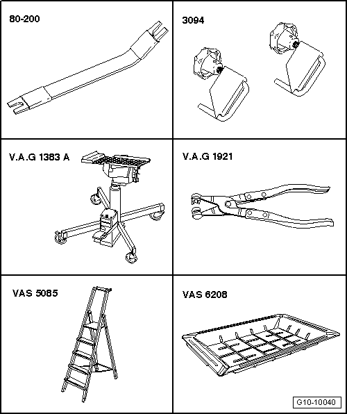
Special tools and workshop equipment required
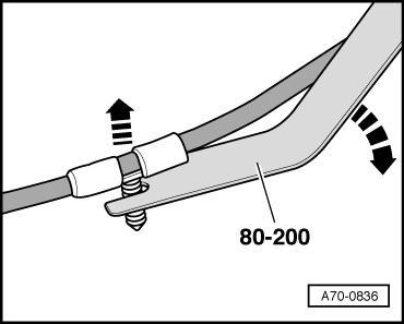
t  Removal lever -80 - 200-
t  Hose clamps, up to 25 mm -3094- (only for vehicles with manual gearbox)
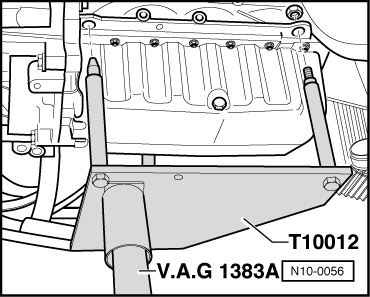
t  Engine and gearbox jack -V.A.G 1383 A-
t  Hose clip pliers -V.A.G 1921-
t  Stepladder -VAS 5085-
t  Drip tray for workshop hoist -VAS 6208-

   
t  Engine bracket -T10012-
  W00-0598
t  Tool set for wiper arms -T10369-
Procedure
  Note
t  The engine is removed from underneath together with the gearbox.
t  All cable ties which are released or cut open when removing must be fitted in the same position when installing.
t  Collect drained coolant in a clean container for re-use or disposal.
  W00-10632
–  Lift off engine cover panel (outside -1- and inside -2-) by pulling up evenly.
  A10-10366
–  Remove cover -1- over battery; to do so, press release tab -arrow-.
  A27-0190
  Caution
Observe notes on procedure for disconnecting the battery → Rep. Gr.27.
–  With ignition switched off, disconnect battery earth cable -arrow-.
  WARNING
Hot steam or hot coolant can escape when expansion tank is opened; cover filler cap with cloth and open carefully.
–  Open filler cap on coolant expansion tank.
  A27-0191
–  Remove both front wheels.
–  Remove centre noise insulation -fasteners 1 ... 3-.
  A10-1565
–  Remove noise insulation (left and right) -fasteners 1 ... 3-.
  A10-1566
–  Remove air intake hose (left-side) by lifting retaining clips -arrows- slightly.
  A10-1834
–  Remove air intake hose (right-side) by lifting retaining clips -arrows- slightly.
  Caution
Seal opening of charge air cooler with a piece of clean foam or similar to prevent coolant from entering.
  A10-1666
–  Place drip tray for workshop hoist -VAS 6208- under engine.
–  Pull out retaining clip at the bottom -arrow-, disconnect coolant hose from radiator and drain off coolant.
–  Move coolant hose clear at air pipe.
  A19-0482
–  Pull cover off air duct (release clips on sides) -arrows-.
  A10-10367
–  Unclip air duct at the bottom by releasing clips -arrows-.
–  Detach air duct (bottom) together with air hose.
  A10-10368
–  Unplug electrical connector -1- at air mass meter -G70-.
–  Detach vent hose -3- and air hose -2-.
–  Unscrew bolt -4- and remove air cleaner housing.
  A10-10369
–  Disconnect coolant hose at bottom of oil cooler -arrow- and drain off remaining coolant.
  A19-0483
–  Remove battery → Rep. Gr.27.
–  Remove battery tray -arrows-.
  A10-1572
Vehicles with manual gearbox:
–  Unclip securing clips -1- and -2- on both selector cables.
–  Pull selector cable end-pieces off selector shaft lever and relay lever.
  A34-0620
–  Remove selector cable support bracket -arrows- from gearbox and place to one side.
  A34-0621
–  Clamp off pressure hose to clutch slave cylinder using a hose clamp -3094-.
–  Detach pressure hose -1- from hose connector by pulling securing clip -arrow- upwards.
  Caution
Do not operate clutch pedal with slave cylinder removed.
  A10-0937
All vehicles (continued):
–  Detach coolant hoses at the connections indicated -arrows-.
  A19-0566
–  Disconnect vacuum hose -arrow- from brake servo.
  A10-10031
–  Remove crankcase breather hose -2-.
–  Move vent hose -4- and vacuum hoses -3- clear at air intake hose.
–  Slacken hose clip -1-.
–  Swing air hose to rear and detach from turbocharger.
  A21-10152
–  Disconnect electrical connector -1- at charge pressure control solenoid valve -N75-.
–  Unscrew nuts and place charge pressure control solenoid valve -N75- on engine (hoses remain connected).
  Note
Disregard -items 2, 3, 4 and 5-.
  A23-10003
–  Detach coolant hoses going to to heat exchanger at bulkhead -arrows-.
  A10-1670
–  Unclip change-over valve for exhaust gas recirculation cooler -N345--item 2- from bracket.
–  Unplug electrical connector -1- and move wiring clear.
–  Remove bolts -arrows-.
  Note
Disregard -items 3, 4, 5 and 6-.
  A15-10345
–  Unplug electrical connector -3- for exhaust gas temperature sender 1 -G235- and electrical connector -4- for Lambda probe -G39-.
–  Move wiring clear.
  Note
Disregard -items 1, 2 and 5-.
  A23-10003
–  Unscrew Lambda probe -3- → Rep. Gr.23.
–  Remove temperature sender before particulate filter -G506--item 5- and move wiring clear.
–  Unbolt bracket -2- for pressure pipes.
–  Detach pressure pipe -4- from particulate filter.
–  Remove exhaust gas pressure sensor 1 -G450- together with pressure pipes.
–  Slacken and remove retaining clamp -1- for particulate filter.
  A26-10173
–  Detach coolant hose -arrow- at coolant expansion tank.
  A10-1582
  Caution
Rules for cleanliness when working on the injection system → Chapter.
  WARNING
t  In extreme cases the fuel lines and the fuel can reach a temperature of 100 °C on vehicles with unit injector engine. Allow the fuel to cool down before disconnecting the lines - danger of scalding.
t  Wear protective gloves.
t  Wear safety goggles.
–  Disconnect fuel supply pipe -2- and fuel return pipe -1- by pulling release tabs.
  A20-1118
–  Detach coolant hose -2- at front of engine.
  Note
Disregard -item 1-.
  A10-1673
–  Detach fuel supply hose -2- and fuel return hose -1- from fuel pipes.
  A10-1684
–  Slacken bolt -1- one turn.
–  Remove bolt -2- and nut -3-.
–  Remove fuel filter with hoses attached.
  Note
  A20-10245
Before removing, mark direction of rotation of poly V-belt with chalk or felt-tipped pen. If the belt runs in the opposite direction when it is refitted, this can cause breakage.
–  Turn the tensioner in the direction of the -arrow- to slacken the poly V-belt.
–  Remove poly V-belt.
  A13-0083
–  Unscrew bolts -arrows- and remove alternator.
  Note
t  If alternator sticks in its bracket, screw bolt back in again down to the last 2 turns.
t  Tap carefully on bolt heads with flat side of hammer to release bushes of alternator mountings.
–  Swivel alternator towards right side of vehicle with wiring connected.
  A27-10035
–  Unplug electrical connector -2-.
–  Unscrew wire -1- and wire clamp -3- at alternator.
–  Lift out alternator.
  A27-0218
–  Unscrew air duct at lock carrier -arrows-.
  A19-0472
–  Unscrew top bolts -upper arrows- for radiator cowl.
  A19-0473
–  Lever off caps on windscreen wiper arms with a screwdriver.
–  Loosen nuts -arrows- several turns.
  A92-0191
–  Apply puller -T10369/1- onto wiper arm -1- as shown illustration.
–  Apply thrust piece -2- onto wiper shaft.
–  Turn bolt -3- in clockwise direction until wiper arm is pulled off wiper shaft.
–  Remove nuts completely and take off wiper arms.
  A92-10125
–  Unclip washer jets -arrow-.
–  Push washer jet through assembly opening back into plenum chamber, leaving hoses connected.
  A92-0135
–  Pull off rubber seal -1- on plenum chamber cover.
–  Detach plenum chamber cover -2-.
  A10-1561
–  Detach engine wiring harness at rear plenum chamber panel.
–  Remove plenum chamber intermediate plate -arrows-.
  A10-1573
–  Remove engine control unit → Rep. Gr.23.
–  Unplug electrical connector -2- for engine wiring harness and move connector clear.
  Note
The electrical connector -1- remains connected.
  A24-0730
–  Release wiring protector for engine wiring harness -arrow- and lift off.
  A10-1574
–  Press the two clips in direction of the -arrows- and remove cover from electronics box in engine compartment.
  A10-10349
–  Unscrew terminal 30 wire -arrow- from electronics box in engine compartment and move it clear.
  A10-1883
–  Open wiring duct brackets -arrows-.
  A10-1575
–  Unclip electrical connector -1- from bracket and unplug it.
–  Open wiring duct bracket located below.
–  Unclip engine control unit wiring harness from wiring duct.
  Note
Disregard -item 2-.
  Note
  A10-10606
Use removal lever -80 - 200- to lever out the wiring clips.
  A70-0836
Vehicles with manual gearbox:
–  Disconnect earth cable -1-.
–  Unplug electrical connector -2-.
–  Push back protective cover and unscrew B+ wire -3- from starter solenoid switch.
  A10-1671
–  Unplug electrical connector -2- for reversing light switch.
–  Unscrew nut -1- and remove bracket with wiring from stud.
  A10-1675
Vehicles with direct shift gearbox:
–  Remove cable tie -arrow- for protective cover -1-.
–  Unplug electrical connector -2-.
–  Push back protective cover and unscrew B+ wire from starter solenoid switch.
–  Disconnect earth cable -3-.
–  Turn retainer catch anti-clockwise and unplug electrical connector -4- at gearbox.
  A10-10607
–  Unplug electrical connector -1-.
  A34-10266
All vehicles (continued):
–  Unplug electrical connector -arrow- at longitudinal member (bottom left).
  A10-10352
–  Loosen bolts -arrows- of assembly mounting for engine approx. 2 turns.
  A10-1642
–  Loosen bolts -arrows- of assembly mounting for gearbox approx. 2 turns.
  A10-1678
–  Unplug electrical connector -1-.
–  Unscrew the bottom bolts -bottom arrows- and remove radiator cowl from below.
  A19-0473
–  Unplug electrical connector -3- at air conditioner compressor.
  Note
Disregard items marked -1- and -2-.
  A10-1677
–  Unplug electrical connector -2- at charge pressure sender -G31-/intake air temperature sender -G42-.
–  Remove bolts -1- and -3-.
–  Disconnect air pipe from air hose -4- and remove pipe downwards.
  WARNING
The air conditioner refrigerant circuit must not be opened.
  Note
To prevent damage to the air conditioner compressor and refrigerant pipes/hoses, ensure that the pipes and hoses are not stretched, kinked or bent.
  A21-10157
–  Unscrew bolts -1- and -2- and tie air conditioner compressor up to lock carrier.
  Note
Disregard -item 3-.
  A10-1677
–  Unplug electrical connector -1- at oil level and oil temperature sender -G266-.
–  Unclip bracket -2- for wire to oil level and oil temperature sender -G266- from subframe.
  A10-10649
–  Unbolt heat shield for drive shaft (right-side) -arrows-.
–  Unbolt drive shafts (left and right) from gearbox flanges.
–  Tie up drive shaft (left-side), push back drive shaft (right-side).
  A10-1633
–  Unscrew bolts -1 ... 3- and remove pendulum support.
  A10-1578
–  Unscrew temperature sender after particulate filter -G527--item 1- from exhaust pipe behind particulate filter and move wiring clear.
–  Unscrew pressure pipe -2- going to exhaust gas pressure sensor 1 -G450-.
  A26-10189
Vehicles with direct shift gearbox:
–  Unscrew bolts -1- for support bracket -D-.
–  Pull off the retaining clip -A- upwards -arrow- and detach selector lever cable from gearbox.
  Note
Disregard items -B- and -C-.
  A37-0659
All vehicles (continued):
–  Remove nuts -1- and -3- and bolt -2- and detach bracket for particulate filter.
  A26-10437
–  Remove front cross-piece for underbody -arrows-.
  Note
To avoid damage, the flexible joints in the front exhaust pipe must not be bent more than 10°.
–  Loosen nuts on clamp -1-.
  A26-0734
–  Unbolt bracket for exhaust system -arrows-.
–  Take out particulate filter: turn it 180° clockwise and at the same time push engine/gearbox assembly slightly forwards.
–  Tie up drive shaft (right-side) towards rear.
  Note
Take care not to damage the surface coating of the drive shaft.
  A26-0735
–  Attach engine bracket -T10012- with securing nut and bolt to cylinder block: approx. 20 Nm.
–  Apply engine and gearbox jack -V.A.G 1383 A- to engine bracket -T10012- and raise engine/gearbox assembly slightly.
  Note
  N10-0056
To unscrew bolts for assembly mounting use stepladder -VAS 5085-.
–  Loosen and remove bolts -arrows- of assembly mounting on engine.
  A10-1642
–  Loosen and remove bolts -arrows- of assembly mounting on gearbox.
  Note
t  Check that all hoses, pipes and wiring connections between engine, gearbox and body have been detached.
t  Carefully guide engine/gearbox assembly when lowering to avoid damage.
t  Make sure there is sufficient clearance from air conditioner compressor.
–  First lower engine/gearbox assembly only slightly.
–  Then swing gearbox end of engine/gearbox assembly forwards and only then lower further.
  A10-1678

Removing engine - vehicles with four-wheel drive with engine codes BMN, BUY > < Removing engine - vehicles with engine codes AZV, BKD