
A3 Mk2
 Note
Note |
|
|
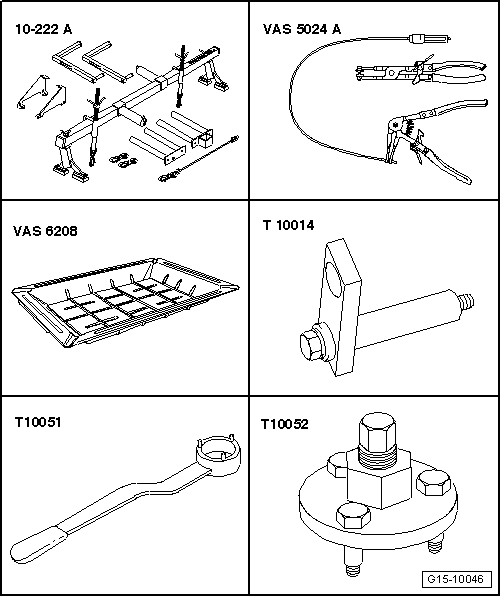
| Special tools and workshop equipment required |
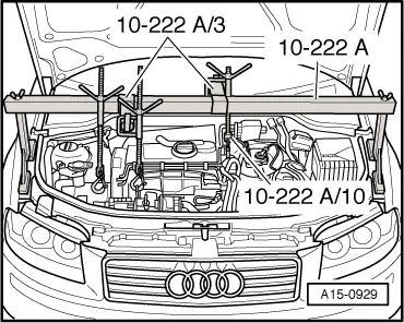
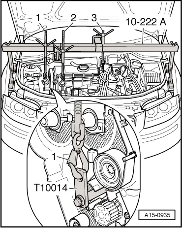
| t | Support bracket -10 - 222 A- |
| t | Spring type clip pliers -VAS 5024 A- |
| t | Drip tray for workshop hoist -VAS 6208- |
| t | Retainer -T10014- |
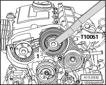
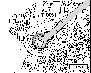
| t | Counterhold tool -T10051- |
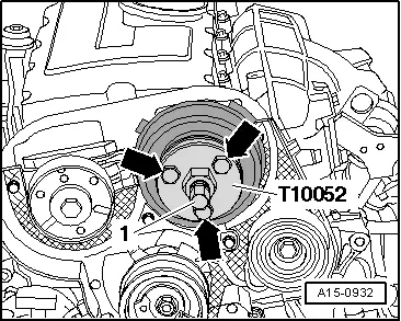
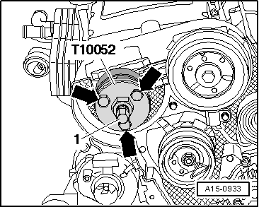
| t | Puller -T10052- |

| t | Hooks -10 - 222 A /10- (with spindle) |
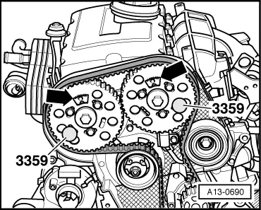
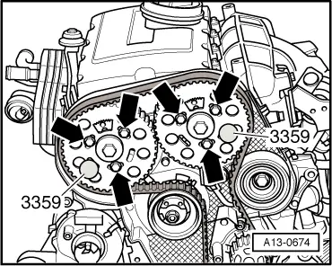
| t | Diesel injection pump locking pin -3359- (2x) |
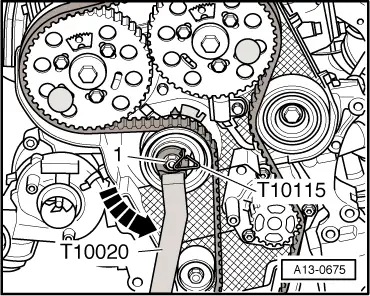
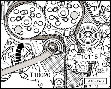
| t | Pin wrench -T10020- |
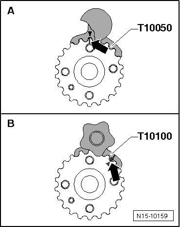
| t | Crankshaft stop -T10050- for engines with circular crankshaft sprocket |
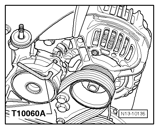
| t | Locking pin -T10060 A- |
| t | Crankshaft stop -T10100- for engines with oval crankshaft sprocket |
|
|
|
|
 Caution
|
|
|
|
|
|
|
|
|
|
Note
|
|
 WARNING
|
|
|
|
Note
|
|
|
|
|
|
|
|
|
|
|
|
|
|
|
|
|
|
|
|
|
|
|
|
|
|
|
|
|
|
|
|
|
|
|
|
|
|
|
|
|
|
|
|
|
|
|
|
|
|
|
|
|
|
Note |
|
|
|
|
|
|
|
|
|
|
|
|
|
|
|
|
|
Note
|
|
Note
|
|
Note
|
|
|
|
|
|
|
|
|
|
|
|
|
|
|
|
|
|
|
|
|
|
|
|
Note
|
|
|
|