| –
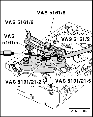
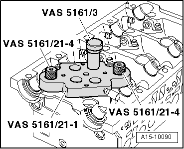
| Screw adapter -VAS 5161/21-2- finger-tight into guide plate. |
| –
| Secure snap-in device -VAS 5161/6- with engaging forks -VAS 5161/5- to cylinder head. |
| –
| Slide knurled spacer ring -VAS 5161/21-5- onto assembly cartridge -VAS 5161/8-. |
| –
| Insert assembly cartridge into guide plate. |
| –
| With cylinder head installed, connect the adapter -VAS 5161/21-2- to compressed air line using a commercially available connection piece, and apply constant air pressure. |
| l
| Air pressure: at least 6 bar |
| –
| Attach pressure fork -VAS 5161/2- to snap-in device and push assembly cartridge down. |
| –
| At the same time, turn knurled screw of assembly cartridge clockwise until tips engage in valve cotters. |
| –
| Move knurled screw back and forth slightly; the valve cotters are thus forced apart and taken up by the assembly cartridge. |
| –
| Release the pressure fork. |
| –
| Take out assembly cartridge with knurled spacer ring, valve spring plate and valve spring. |
|
|
|

 Note
Note