
Removing and installing toothed belt for 4-cylinder TDI engine - large engine support
 Note
Note |
|
|
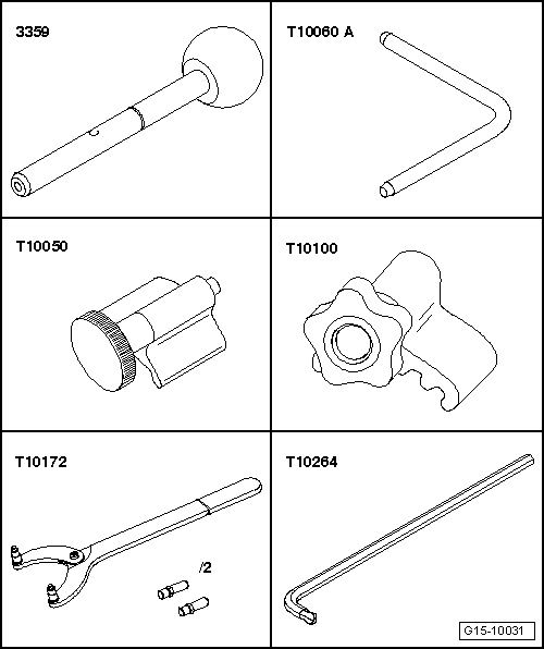
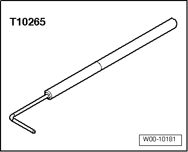
| Special tools and workshop equipment required |
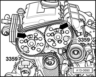
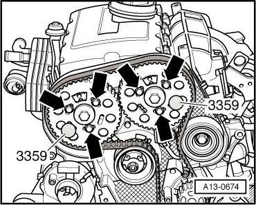
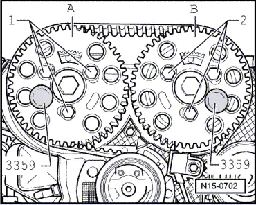
| t | Diesel injection pump locking pin -3359- (2x) |
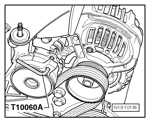
| t | Locking pin -T10060 A- |
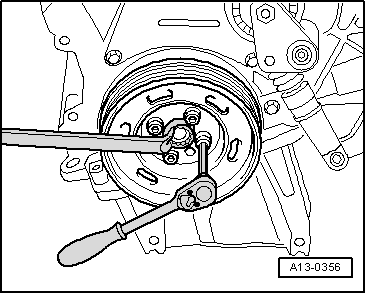
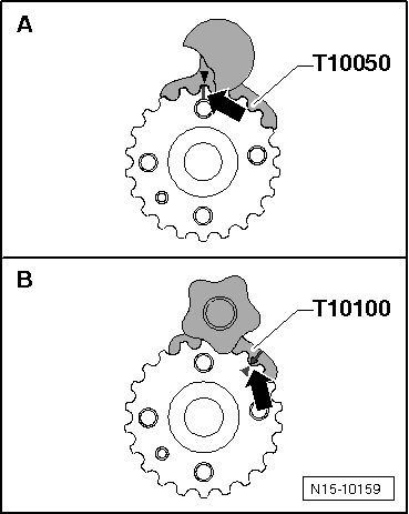
| t | Crankshaft stop -T10050- for engines with circular crankshaft sprocket |
| t | Crankshaft stop -T10100- for engines with oval crankshaft sprocket |
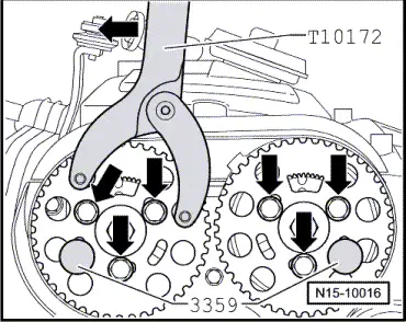
| t | Counter-hold tool -T10172- with pin -T10172/4- |
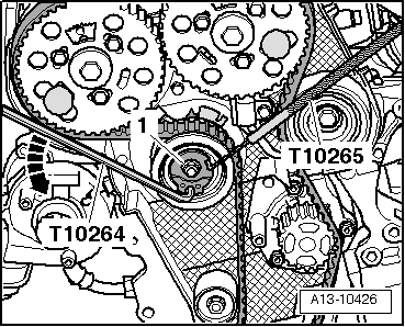
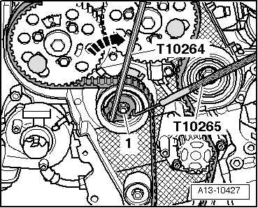
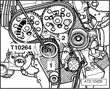
| t | Special wrench, long reach -T10264- |
|
|
|
|
|
|
|
|
 Caution
 WARNING
|
|
|
|
|
|
Note |
|
|
|
|
|
|
|
|
|
|
|
|
|
|
|
|
|
|
|
Note
|
|
Note
|
|
|
|
|
|
|
|
|
|
Note
Note
|
|
|
|
|
|
|
|
Note
|
|
Note
|
|
| Component | Nm | ||||
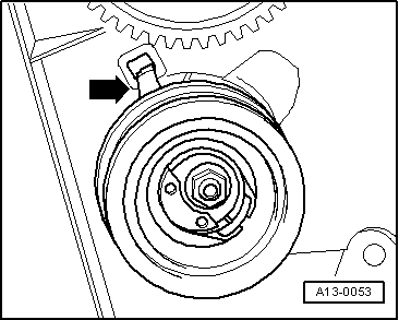
| Tensioning roller for toothed belt to cylinder head | 20 + 45° 1) | ||||
| Camshaft sprocket to hub | 25 | ||||
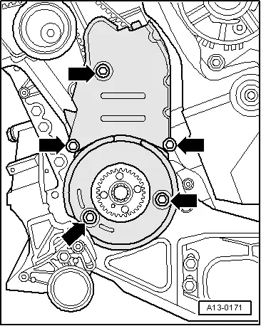
| Toothed belt cover (bottom) to cylinder block | 10 2) | ||||
| Toothed belt cover (centre) to cylinder block | 10 2) | ||||
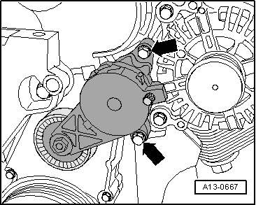
| Tensioner for poly V-belt to bracket for ancillaries | 23 | ||||
| |||||