
A3 Mk2
| Connection diagram for vacuum lines |
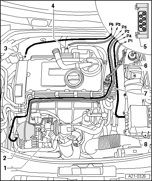
| 1 - | Mechanical exhaust gas recirculation valve |
| q | Checking → Chapter |
| q | Removing and installing → Chapter |
| 2 - | Vacuum reservoir |
| 3 - | To vacuum unit for charge pressure control |
| 4 - | To vacuum unit for exhaust gas recirculation cooler change-over |
| 5 - | Solenoid valve block |
| q | With exhaust gas recirculation valve -N18- |
| q | With charge pressure control solenoid valve -N75- |
| q | With exhaust gas recirculation cooler change-over valve -N345- |
| q | Connection diagram → Chapter |
| 6 - | Vacuum supply line |
| q | From tandem pump to solenoid valve block |
| 7 - | Tandem pump |
| 8 - | Air cleaner housing |
| q | With connection for vent hose |