
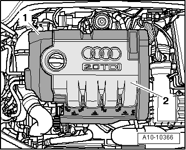
A3 Mk2
|
 Note
Note
|
|
Note
|
|
|
|
Note
|
|
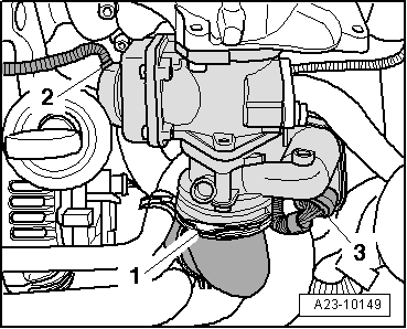
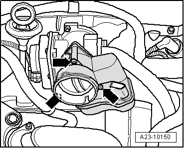
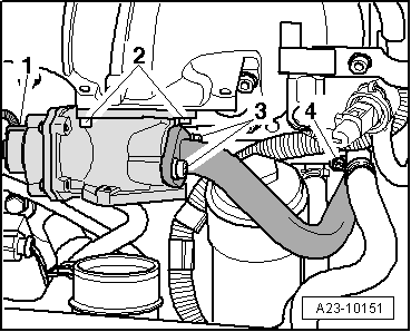
| Component | Nm |
| Exhaust gas recirculation valve -N18- with exhaust gas recirculation potentiometer -G212- to intake manifold | 10 |
| Intake manifold flap motor -V157- to exhaust gas recirculation valve -N18- with exhaust gas recirculation potentiometer -G212- | 10 |
| EGR connecting pipe to exhaust gas recirculation valve -N18- with exhaust gas recirculation potentiometer -G212- | 22 |