
A3 Mk2
|
|
|
|
|
 Note
Note
|
|
Note
|
|
|
|
|
|
|
|
|
|
Note
|
|
|
|
|
|
Note
|
|
|
|
Note
|
|
| Component | Nm | ||||
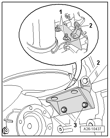
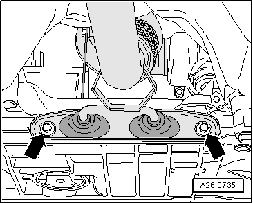
| Bracket for exhaust system to subframe | 23 | ||||
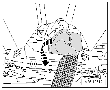
| Front exhaust pipe to turbocharger | 7 | ||||
| Bracket for particulate filter to particulate filter | 23 | ||||
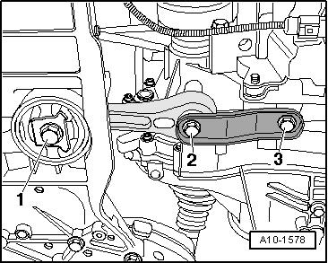
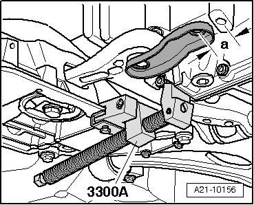
| Pendulum support to gearbox | Manual gearbox → Rep. Gr.34, automatic gearbox → Rep. Gr.37 | ||||
| Heat shield to cylinder block | 35 | ||||
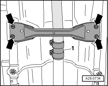
| Underbody cross member (front) to body | 23 | ||||
| Pressure pipe to particulate filter | 40 | ||||
| |||||