
A3 Mk2
|
|
|
 Caution
|
|
|
|
|
|
|
|
|
|
|
|
 Note
Note
|
|
Note
|
|
|
|
|
|
|
|
|
|
|
|
|
|
|
|
|
|
Note
Note
|
|
| Component | Nm | |||
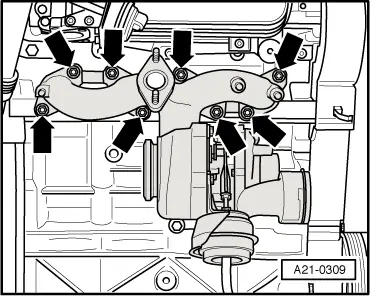
| Exhaust manifold/turbocharger to cylinder head | 25 1) | |||
| Heat shield to exhaust manifold/turbocharger | 25 | |||
| EGR connecting pipe to: | Change-over flap | 20 | ||
| Exhaust manifold | 25 | |||
| Oil supply pipe to turbocharger | 22 | |||
| Bracket for oil supply pipe to exhaust manifold | 25 | |||
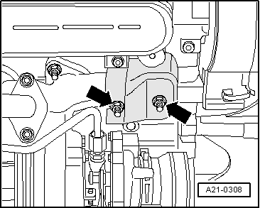
| Bracket for turbocharger to: | Cylinder block | 40 | ||
| Turbocharger | 20 | |||
| Oil return pipe to cylinder block | 30 | |||
| Oil supply pipe to oil filter bracket | 22 | |||
| Oil pressure switch to oil filter bracket | 20 | |||
| ||||