
A3 Mk2
| Diagram of coolant hose connections |
 Note
Note| t | Blue = Large coolant circuit. |
| t | Red = Small coolant circuit with heating circuit. |
| t | Orange = Coolant circuit for turbocharger. |
| t | Arrows show direction of coolant flow. |
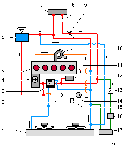
| 1 - | Radiator |
| q | If renewed, refill system with fresh coolant |
| 2 - | Non-return valve |
| q | Arrow indicates direction of flow |
| 3 - | Thermostat with housing |
| 4 - | Coolant pump |
| 5 - | Cylinder head and cylinder block |
| q | If renewed, refill system with fresh coolant |
| 6 - | Coolant expansion tank |
| q | With filler cap and pressure relief valve |
| q | Checking pressure relief valve → Anchor |
| 7 - | Heat exchanger for heater |
| q | If renewed, refill system with fresh coolant |
| 8 - | Bleeder screw |
| 9 - | Restrictor |
| 10 - | Turbocharger |
| 11 - | Coolant temperature sender -G62- |
| 12 - | Engine oil cooler |
| q | If renewed, refill system with fresh coolant |
| 13 - | Thermostat |
| q | For coolant circuit for gearbox |
| 14 - | Continued coolant circulation pump -V51- |
| 15 - | Solenoid for coolant circuit -N492- |
| 16 - | Heat exchanger |
| q | For gear oil |
| 17 - | Auxiliary radiator (left-side) |
| q | For coolant circuit for gearbox |
| q | If renewed, refill system with fresh coolant |