
A3 Mk2
| Valve gear - exploded view |
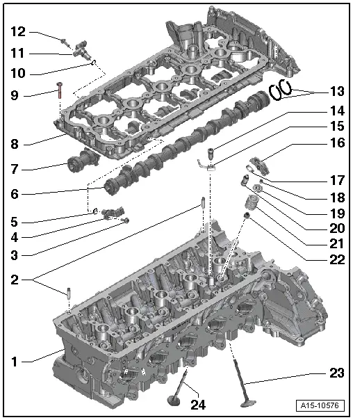
| 1 - | Cylinder head |
| q | Checking valve guides → Chapter |
| 2 - | Dowel pins |
| 3 - | Bolt |
| q | Tightening torque → Rep. gr.28 |
| 4 - | Hall sender 3 -G300- |
| q | Exhaust side |
| q | Removing and installing → Rep. gr.28 |
| 5 - | O-ring |
| q | Renew |
| 6 - | Inlet camshaft |
| q | Removing and installing → Chapter |
| q | Measuring axial clearance → Chapter |
| q | Measuring radial clearance → Chapter |
| q | Runout: max. 0.04 mm |
| 7 - | Exhaust camshaft |
| q | With additional cam for high-pressure pump |
| q | Removing and installing → Chapter |
| q | Measuring axial clearance → Chapter |
| q | Measuring radial clearance → Chapter |
| q | Runout: max. 0.04 mm |
| 8 - | Retaining frame |
| q | With integrated camshaft bearings |
| 9 - | Bolt |
| q | To avoid damage to retaining frame for camshafts, refer to tightening torque and sequence → Fig. |
| 10 - | O-ring |
| q | Renew |
| 11 - | Hall sender -G40- |
| q | Inlet side |
| q | Removing and installing → Rep. gr.28 |
| 12 - | Bolt |
| q | Tightening torque → Rep. gr.28 |
| 13 - | Rectangular section seals |
| 14 - | Bolt |
| q | With pressure relief valve |
| q | 27 Nm |
| 15 - | Oil spray jet |
| 16 - | Roller rocker finger |
| q | Mark installation position for re-installation |
| q | Check roller bearings for ease of movement |
| q | Lubricate contact surface before installing |
| q | Assembly: attach to hydraulic compensation element -item 20- using securing clip -item 17- |
| 17 - | Securing clip |
| q | Not supplied separately |
| q | Check for firm attachment |
| 18 - | Valve cotters |
| 19 - | Valve spring plate |
| 20 - | Hydraulic valve compensation element |
| q | Clipped into roller rocker finger -item 16- |
| q | Checking → Chapter |
| q | Mark installation position for re-installation |
| q | Lubricate contact surface before installing |
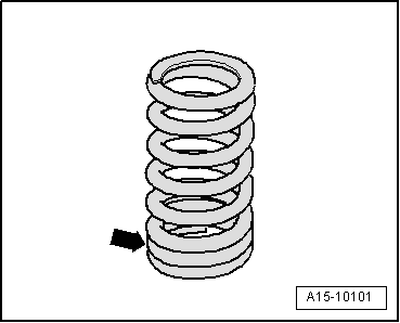
| 21 - | Valve spring |
| q | Installation position → Fig. |
| 22 - | Valve stem oil seal |
| q | Renewing with cylinder head installed → Chapter |
| q | Renewing with cylinder head removed → Chapter |
| 23 - | Inlet valve |
| q | Must not be machined; only grinding-in is permissible |
| q | Mark installation position for re-installation |
| q | Checking → Chapter |
| q | Valve dimensions → Chapter |
| q | Checking valve guides → Chapter |
| 24 - | Exhaust valve |
| q | Must not be machined; only grinding-in is permissible |
| q | Mark installation position for re-installation |
| q | Checking → Chapter |
| q | Valve dimensions → Chapter |
| q | Checking valve guides → Chapter |
|
|
 Note
Note Caution
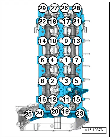
| Stage | Bolts | Tightening torque/angle specification | ||
| 1. | -1 … 29- | Screw in by hand until bolt heads make contact with retaining frame | ||
| 2. | -1 … 29- | Continue tightening 1 turn at a time in several stages until retaining frame makes full contact with cylinder head and a torque of 8 Nm is reached | ||
| 3. | -1 … 29- | 8 Nm 1) | ||
| 4. | -1 … 29- | turn 90° further | ||
| ||||