
A3 Mk2
| Sump (bottom section), sump (top section), oil pump - exploded view |
 Note
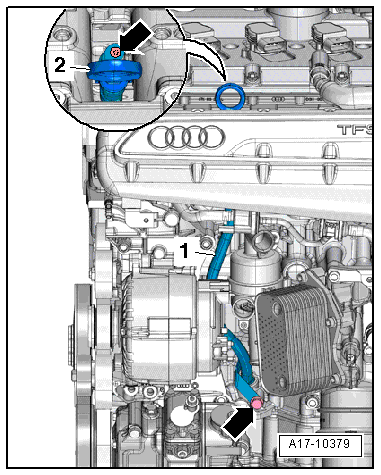
Note| Oil spray jet and pressure relief valve → Fig. |
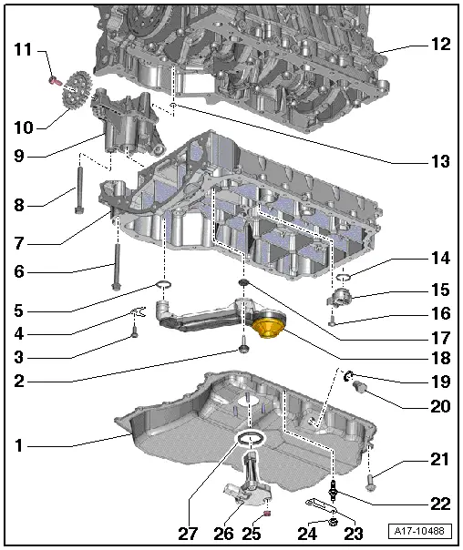
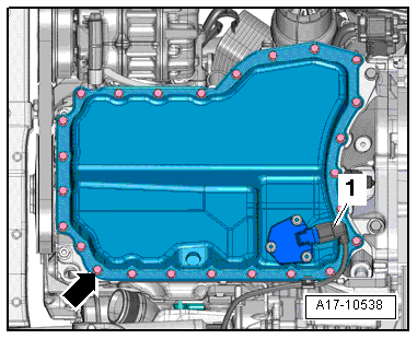
| 1 - | Sump (bottom section) |
| q | Removing and installing → Chapter |
| q | Apply sealant when installing; refer to → Electronic parts catalogue |
| 2 - | Bolt |
| q | With bush and rubber ring |
| q | 9 Nm |
| 3 - | Bolt |
| q | 9 Nm |
| 4 - | Bracket |
| q | For oil intake pipe |
| 5 - | Seal |
| q | Renew |
| 6 - | Bolt |
| q | Renew |
| q | Tightening torque and sequence → Fig. |
| 7 - | Sump (top section) |
| q | Removing and installing → Chapter |
| q | Apply sealant when installing; refer to → Electronic parts catalogue |
| 8 - | Bolt |
| q | 20 Nm |
| 9 - | Oil pump |
| q | Do not dismantle |
| q | Removing and installing → Chapter |
| 10 - | Drive chain sprocket |
| q | For oil pump |
| q | Installation position: lettering must be legible from outside |
| 11 - | Bolt |
| q | Renew |
| q | 20 Nm + turn 90° further |
| 12 - | Cylinder block |
| 13 - | O-ring |
| q | Renew |
| 14 - | O-ring |
| q | Renew |
| 15 - | Connection |
| q | For oil return |
| 16 - | Bolt |
| q | 9 Nm |
| 17 - | Rubber grommet |
| 18 - | Oil intake pipe |
| 19 - | Seal |
| q | Renew |
| 20 - | Oil drain plug |
| q | 25 Nm |
| 21 - | Bolt |
| q | Renew |
| q | Tightening torque and sequence → Fig. |
| 22 - | Centre hex stud |
| q | Tightening torque and sequence → Fig. |
| 23 - | Bracket |
| 24 - | Nut |
| q | 9 Nm |
| 25 - | Nut |
| q | 9 Nm |
| 26 - | Oil level and oil temperature sender -G266- |
| q | Removing and installing → Chapter |
| 27 - | Seal |
| q | Renew |
Note
|
|
| Stage | Bolts | Tightening torque/angle specification |
| 1. | -arrow- | Screw in bolts by hand until they make contact |
| 2. | -arrow- | 8 Nm in diagonal sequence |
| 3. | -arrow- | Turn 45° further in diagonal sequence |
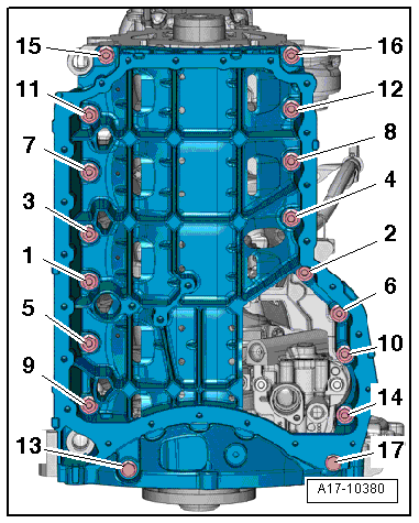
Note
|
|
| Stage | Bolts | Tightening torque/angle specification |
| 1. | -1 … 17- | Screw in bolts by hand until they make contact |
| 2. | -1 … 17- | 20 Nm |
| 3. | -1 … 17- | turn 90° further |
|
|