audi Workshop Repair Guides

Audi Workshop Service and Repair Manuals

Removing and installing continued coolant circulation pump V51 > < Checking thermostat
Removing and installing coolant pipe
Special tools and workshop equipment required
   
t  Locking pin -T10060 A-
Removing
  Note
Collect drained coolant in a clean container for re-use or disposal.
  Caution
Observe notes on procedure for disconnecting the battery → Rep. Gr.27.
  W00-10235
–  Remove the moulded insert for tools from beneath the luggage compartment floor cover.
–  Unscrew the lid -arrow- of the battery compartment.
–  Remove moulded insert from top of battery.
  A27-0230
–  With ignition switched off, disconnect earth wire -arrow- at battery.
–  Remove thermostat housing → Chapter.
–  Pull out oil dipstick.
  Note
  A27-10012
Mark rotation direction of poly V-belt with chalk or a felt-tipped pen. If the belt runs in the opposite direction when it is refitted, this can cause breakage.
–  Turn tensioner in direction of -arrow- to slacken poly V-belt and lock in position with locking pin -T10060 A-.
  A13-10345
–  Detach vacuum hose -2- from air intake hose (if fitted).
–  Detach air hose -1- at the throttle valve module -J338-.
–  Unplug electrical connector for air mass meter -G70- -item 3-.
–  Unscrew air cleaner housing (upper section) -arrow-.
–  Take out filter element.
  A10-1879
–  Pull cover -1- off air duct (release clips on sides).
–  Unclip air duct -2-.
  A10-1878
–  Unscrew air cleaner housing (lower section) -arrows-.
  A10-1880
–  Disconnect secondary air hose at the position marked with an -arrow-.
–  Move air hose to secondary air pump clear.
  A10-1791
–  Remove centre noise insulation -fasteners 1 ... 3-.
  A10-1565
–  Move coolant hose at bottom of radiator cowl clear.
–  Detach electrical connector -3- at secondary air pump motor -V101- and move wire clear.
–  Unscrew bracket -2- for coolant pipe going to gearbox oil cooler on vehicles with direct shift gearbox.
–  Remove bolts -1-.
–  Loosen bolt -4- and remove secondary air pump with bracket.
  A26-0833
–  Unplug electrical connector -1- for magnetic clutch at AC compressor and move electrical wiring clear.
  WARNING
The air conditioner refrigerant circuit must not be opened.
–  Unscrew bolts -arrow- for air conditioner compressor.
–  Tie up air conditioner compressor together with refrigerant hoses at front of longitudinal member (refrigerant hoses remain connected).
  A10-1894
–  Unhook connector -arrow- for engine speed sender -G28- from bracket on guide tube for oil dipstick.
  A28-0073
–  Unscrew bolt -3- and pull out guide tube for oil dipstick -2-.
–  Unscrew bolt -4- and detach vacuum reservoir -1- from manifold.
–  Move vacuum reservoir to side (hoses remain attached).
  A15-0981
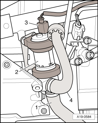
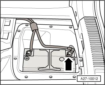
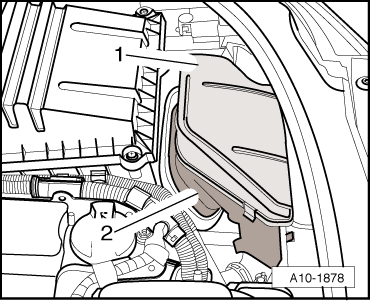
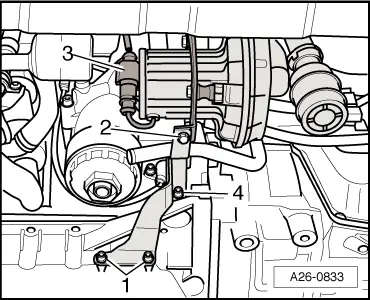
–  Unplug electrical connector -3- at continued circulation coolant pump -V51--Item 2-.
–  Pull the pump downwards out of the rubber retainers on bracket. If necessary, spray rubber retainers with silicone-free lubricant.
–  Unscrew bracket for continued circulation coolant pump -V51-.
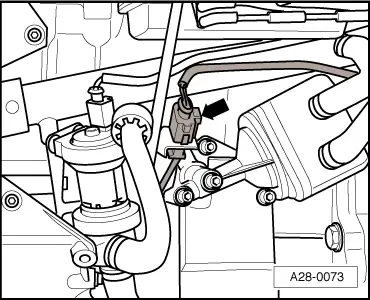
–  Unclip bracket for wiring harness (right-side) from coolant pipe.
–  Disconnect wiring harness (left-side) from bracket at coolant pipe.
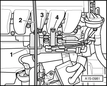
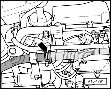
–  Disconnect coolant hose to oil cooler at coolant pipe.
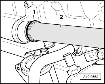
–  Pull coolant pipe out of cylinder block.
Installing
Installation is carried out in the reverse order; note the following:
  Note
Renew O-rings.
–  Before installing, clean and smoothen sealing surface for O-ring in cylinder block.
  A19-0584
–  Lubricate new O-ring -1- with “G 12+” and push onto coolant pipe -2-.
–  Push coolant pipe into bore on cylinder block.
–  Install thermostat housing → Chapter.
–  Install air conditioner compressor → Rep. Gr.87.
–  Install poly V-belt → Chapter.
–  Fill cooling system → Anchor.
Tightening torque
  A19-0552
ComponentNm
Bracket for coolant pump to bracket for ancillary units10


Removing and installing continued coolant circulation pump V51 > < Checking thermostat