audi Workshop Repair Guides

Audi Workshop Service and Repair Manuals

Valve dimensions > < Renewing valve stem oil seals with cylinder head installed
Renewing valve stem oil seals with cylinder head removed
   
Renewing valve stem oil seals with cylinder head removed
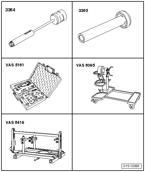
Special tools and workshop equipment required
t  Valve stem seal puller -3364-
t  Valve stem seal fitting tool -3365-
t  Removal / installing device for valve cotters -VAS 5161- with guide plate -VAS 5161/25-
t  Engine and gearbox support -VAS 6095-
t  Cylinder head tensioning device -VAS 6419-

Special tools and workshop equipment required
t 
Procedure
–  Remove camshafts → Chapter.
–  Mark original positions of roller rocker fingers and hydraulic compensation elements for reinstallation.
–  Remove roller rocker fingers together with hydraulic compensation elements and put down on a clean surface.
   
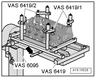
–  Attach tensioning device -VAS 6419- to engine and gearbox support -VAS 6095-.
–  Secure cylinder head in tensioning device -VAS 6419- as illustrated.
–  Connect compressed air line to tensioning device -VAS 6419-.
–  Using lever -arrow-, slide air pad under combustion chamber where valve stem oil seals are to be removed.
–  Apply just enough compressed air to bring air pad into contact with valve heads.
  A15-10529
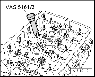
–  Apply drift -VAS 5161/3- to valve spring plate and knock valve cotters loose using a plastic hammer.
  A15-10110
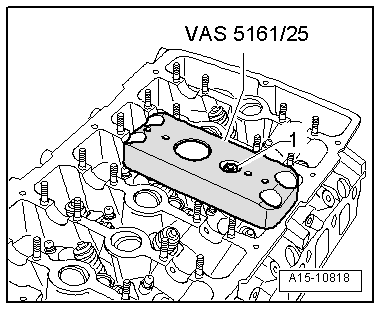
–  Fit guide plate -VAS 5161/25- from removal / installing device for valve cotters -VAS 5161- on cylinder head.
–  Secure guide plate with one nut -1-.
  A15-10818
Procedure for rear row of valves:
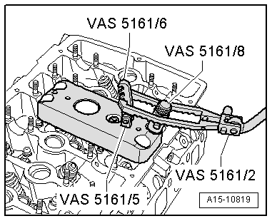
–  Screw snap-in device -VAS 5161/6- with engaging fork -VAS 5161/5- into guide plate.
–  Insert assembly cartridge -VAS 5161/8- into guide plate.
–  Attach pressure fork -VAS 5161/2- to snap-in device and push assembly cartridge down.
–  At the same time, turn knurled screw of assembly cartridge clockwise until tips engage in valve cotters.
–  Move knurled screw back and forth slightly; the valve cotters are thus forced apart and taken up by the assembly cartridge.
–  Release the pressure fork.
–  Remove assembly cartridge.
–  Detach guide plate and turn to one side.
–  Remove valve spring with valve spring plate.
  A15-10819
Procedure for front row of valves:
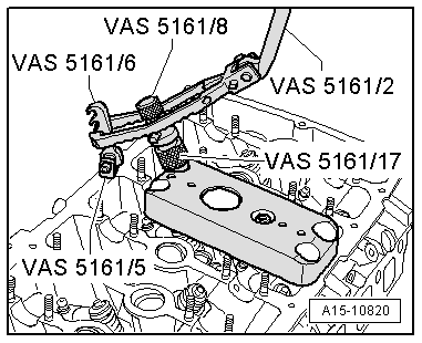
–  Screw snap-in device -VAS 5161/6- with engaging fork -VAS 5161/5- onto cylinder head.
–  Slide knurled spacer ring -VAS 5161/17- onto assembly cartridge -VAS 5161/8-.
–  Insert assembly cartridge into guide plate.
–  Attach pressure fork -VAS 5161/2- to snap-in device and push assembly cartridge down.
–  At the same time, turn knurled screw of assembly cartridge clockwise until tips engage in valve cotters.
–  Move knurled screw back and forth slightly; the valve cotters are thus forced apart and taken up by the assembly cartridge.
–  Release the pressure fork.
–  Remove assembly cartridge.
–  Detach guide plate and turn to one side.
–  Remove valve spring with valve spring plate.
  A15-10820
Continuation for both rows of valves:
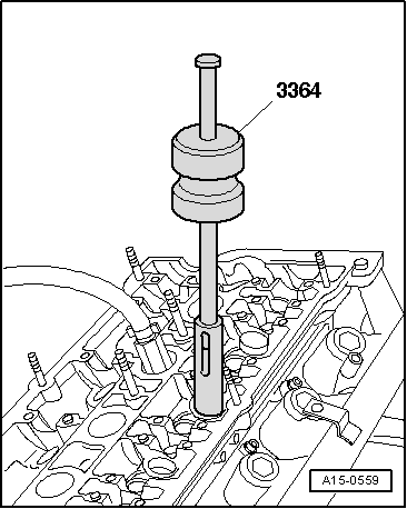
–  Remove valve stem oil seals using the valve stem seal puller -3364-.
  Note
t  To press on the green-coloured valve stem seals (as currently supplied), the valve stem oil seal fitting tool -3365- must be drilled out to Ø 10.5 mm.
t  Mark the drilled-out fitting tool so it can be used again later.
  A15-0559
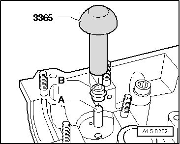
t  A plastic sleeve -A- is included with the new valve stem oil seals.
–  Fit plastic sleeve -A- onto the valve stem to prevent damage to the new valve stem oil seal -B-.
–  Lightly lubricate sealing lip of valve stem oil seal.
–  Slip valve stem oil seal over plastic sleeve.
–  Carefully press the valve stem oil seal onto valve guide using fitting tool -3365-.
–  Remove plastic sleeve.
  A15-0282
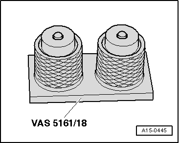
If valve cotters have been removed from assembly cartridge, they need to be put into insertion device -VAS 5161/18- first.
l  Larger diameter of valve cotters faces upwards.
  A15-0445
–  Install valve spring and valve spring plate.
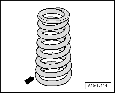
Position of valve spring:
l  The larger diameter -arrow- faces the cylinder head.
  A15-10114
Procedure for rear row of valves:
–  Bolt guide plate onto cylinder head again, as shown in the illustration.
–  Insert assembly cartridge into guide plate.
–  Push pressure fork down and pull knurled screw upwards, while turning screw in both directions – this will insert the valve cotters.
–  Release the pressure fork with knurled screw still in pulled position.
  A15-10819
Procedure for front row of valves:
–  Insert assembly cartridge with knurled spacer ring into guide plate.
–  Push pressure fork down and pull knurled screw upwards, while turning screw in both directions – this will insert the valve cotters.
–  Release the pressure fork with knurled screw still in pulled position.
–  Install camshafts → Anchor.
–  Install spark plugs → Booklet808.
  Note
t  After installing camshafts, wait for approx. 30 minutes before starting engine. Hydraulic valve compensation elements have to settle (otherwise valves will strike pistons).
t  After working on the valve gear, turn the engine carefully at least 2 rotations to ensure that none of the valves make contact when the starter is operated.
  A15-10820

Valve dimensions > < Renewing valve stem oil seals with cylinder head installed