
A3 Mk2
|

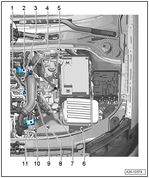
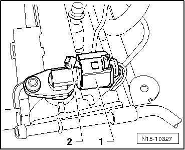
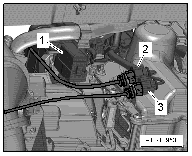
| 1 - | Fuel pressure regulating valve -N276- |
| q | Fitting location → Fig. |
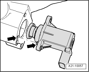
| 2 - | High-pressure pump with fuel pressure regulating valve -N276- |
| q | Removing and installing → Chapter |
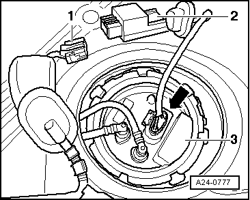
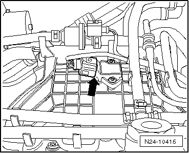
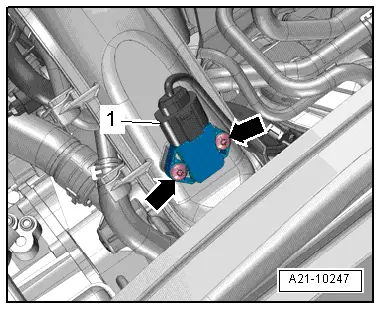
| 3 - | Activated charcoal filter solenoid valve 1 -N80- |
| q | Fitting location → Fig. |
| 4 - | Intake air temperature sender -G42- and intake manifold pressure sender -G71- |
| q | Fitting location → Fig. |
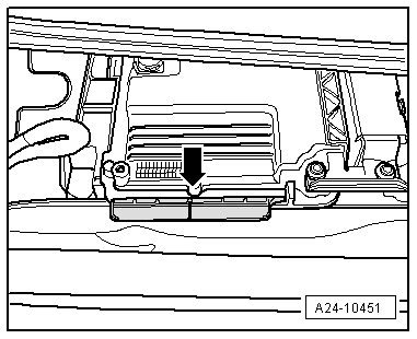
| 5 - | Engine control unit -J623- |
| q | Fitting location → Fig. „„Engine control unit -J623-““ |
| q | Removing and installing → Chapter „Renewing engine control unit -J623-“ |
| 6 - | Knock sensor 1 -G61- |
| q | Fitting location → Fig. |
| q | Removing and installing → Chapter „Removing and installing knock sensor 1 -G61-“ |
| q | 20 Nm |
| 7 - | Engine speed sender -G28- |
| q | Fitting location → Fig. |
| q | Removing and installing → Chapter |
| 8 - | Lambda probe -G39- and Lambda probe heater -Z19- |
| q | Fitting location → Fig. |
| q | Removing and installing → Chapter |
| 9 - | Lambda probe after catalytic converter -G130- and Lambda probe heater 1 after catalytic converter -Z29- |
| q | Fitting location → Fig. |
| q | Removing and installing → Chapter |
| 10 - | Camshaft control valve 1 -N205- |
| q | Fitting location → Fig. |
| q | Removing and installing, refer to engine - mechanics → Rep. gr.15 |
| 11 - | Ignition coils with output stages |
| q | Removing and installing → Chapter |
| q | Ignition coil 1 with output stage -N70- |
| q | Ignition coil 2 with output stage -N127- |
| q | Ignition coil 3 with output stage -N291- |
| q | Ignition coil 4 with output stage -N292- |
| q | Puller -T40039- is required for removing ignition coils from cylinder head. |
|
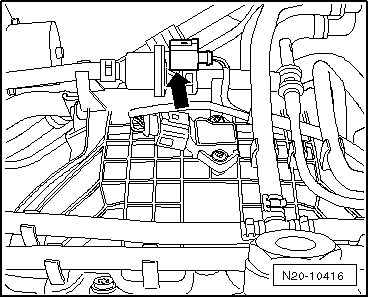
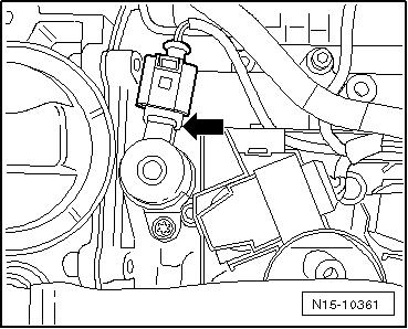
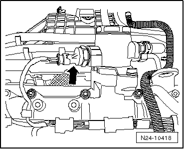
| 1 - | Hall sender -G40- (camshaft position sensor) |
| q | Fitting location: beneath engine cover panel → Fig. |
| q | Removing and installing → Chapter |
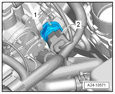
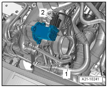
| 2 - | Throttle valve module -J338-, throttle valve drive for electric throttle -G186- |
| q | Throttle valve drive angle sender 1 for electric throttle -G187- and throttle valve drive angle sender 2 for electric throttle -G188- |
| q | After throttle valve module -J338- or engine control unit has been renewed, throttle valve must be re-adapted to engine control unit -J623- |
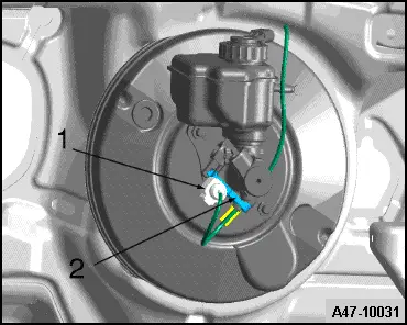
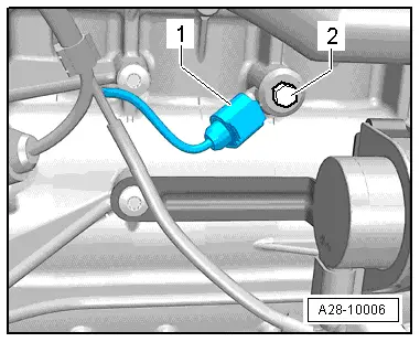
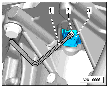
| 3 - | Fuel pressure sender -G247- |
| q | Fitting location → Fig. |
| q | Removing and installing → Chapter |
| 4 - | Charge pressure sender -G31- / intake air temperature sender 2 -G299- |
| q | Fitting location → Fig. |
| q | Removing and installing, refer to engine - mechanics → Rep. gr.21 |
| 5 - | Clutch position sender -G476- |
| q | Only fitted on vehicles with manual gearbox |
| q | Fitting location → Fig. |
| q | Removing and installing, see Power transmission, clutch → Rep. gr.30 |
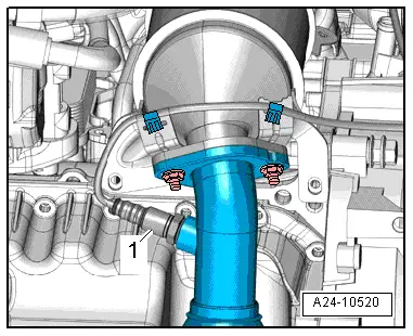
| 6 - | Radiator outlet coolant temperature sender -G83- |
| q | Fitting location → Fig. |
| q | Removing and installing, refer to engine - mechanics → Rep. gr.19 |
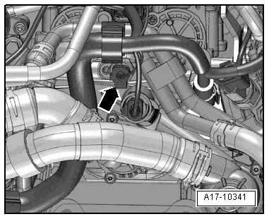
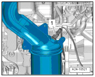
| 7 - | Coolant temperature sender -G62- |
| q | Fitting location → Fig. |
| 8 - | Electrical connectors for Lambda probes |
| q | Fitting locations → Fig. |
| 9 - | Oil pressure switch -F1- |
| q | Removing, installing and checking; engine - mechanics → Rep. gr.17 |
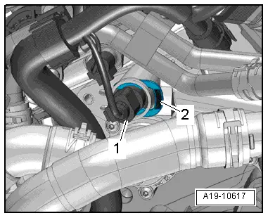
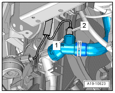
| 10 - | Charge pressure control solenoid valve -N75- |
| q | Located directly on turbocharger → Fig. |
| 11 - | Turbocharger air recirculation valve -N249- |
| q | Located directly on turbocharger → Fig. |
| A - | Injectors |
| q | Removing and installing → Chapter |
| q | Injector, cylinder 1 -N30- |
| q | Injector, cylinder 2 -N31- |
| q | Injector, cylinder 3 -N32- |
| q | Injector, cylinder 4 -N33- |
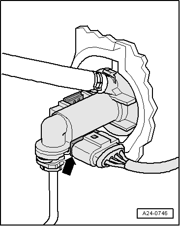
| B - | Brake light switch - F- and brake pedal switch -F63- |
| q | Fitting location → Fig. |
| q | For removing and installing refer to Brake system → Rep. gr.45 |
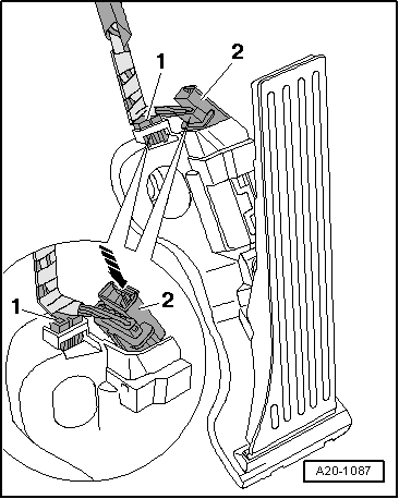
| C - | Accelerator position sender -G79- and accelerator position sender 2 -G185- |
| q | Fitting location → Fig. |
| q | On accelerator pedal (both senders are accommodated in one housing) |
| q | If accelerator pedal module or engine control unit is renewed, kick-down function must be adapted on vehicles with automatic gearbox |
| q | Removing and installing; Fuel supply system, petrol engines → Rep. gr.20 |
| D - | Fuel pump control unit -J538- |
| q | Fitting location → Fig. |
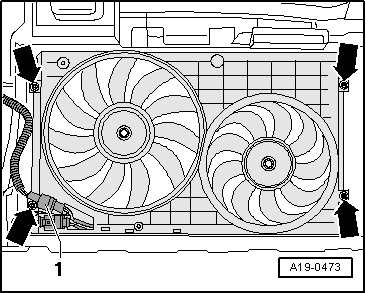
| E - | Radiator fan control unit -J293- |
| q | Fitting location → Fig. |
| q | Removing and installing, refer to engine - mechanics → Rep. gr.19 |
| F - | Relay and fuse holder in electronics box |
| q | Relay and fuse assignment see → Current flow diagrams, Electrical fault finding and Fitting locations |
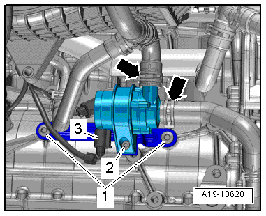
| G - | Coolant circulation pump -V50- |
| q | Fitting location → Fig. |
|
|
|
|
|
|
|
|
|
|
|
|
|
|
|
|
|
|
|
|
|
|
|
|
|
|
|
|
|
|
|
|
 Note
Note
|
|
|
|
|
|
|
|
|
|
|
|
|
|
|
|