
A3 Mk2
|

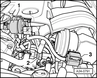
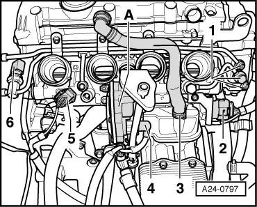
| 1 - | Activated charcoal filter solenoid valve 1 -N80- |
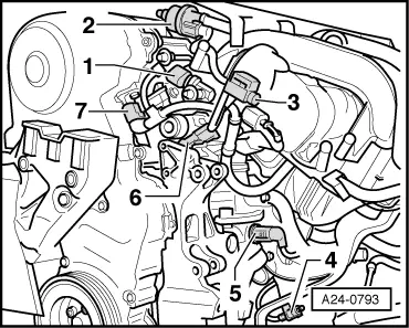
| 2 - | Motronic control unit -J220- |
| q | Removing and installing → Chapter |
| 3 - | Exhaust gas recirculation valve -N18- with exhaust gas recirculation potentiometer -G212- |
| q | Not fitted on engines with code letters BHD, BMB, BLY and BVZ |
| q | → Fig. |
| 4 - | Camshaft control valve 1 -N205- |
| q | → Fig. |
| q | Removing and installing → Rep. Gr.15 |
| 5 - | 6-pin connector |
| q | For Lambda probe -G39- and Lambda probe heater -Z19- (black) |
| q | For Lambda probe 2 -G108- and Lambda probe heater 2 -Z28- (brown); “not fitted on engines with code letters BHD, BLY, BMB, BVY and BVZ” |
| q | → Fig. |
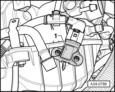
| 6 - | Coolant temperature sender -G62- (4-pin) |
| q | → Fig. |
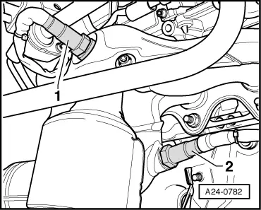
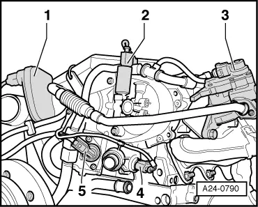
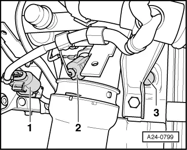
| 7 - | Fuel pressure regulating valve -N276- |
| q | → Fig. |
| 8 - | Single-plunger high-pressure pump |
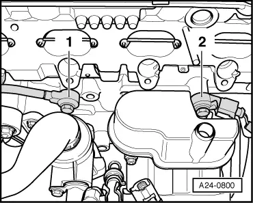
| 9 - | Radiator outlet coolant temperature sender -G83- |
| q | → Fig. |
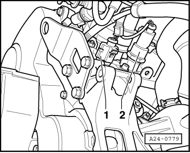
| 10 - | Intake air temperature sender 2 -G299- |
| q | → Fig. |
| 11 - | Intake manifold pressure sender -G71- with intake air temperature sender -G42- |
| q | → Fig. |
| 12 - | Throttle valve module -J338-, throttle valve drive for electric throttle -G186- |
| q | Throttle valve drive angle sender 1 for electric throttle -G187- and throttle valve drive angle sender 2 for electric throttle -G188- |
| q | Perform adaption after renewing throttle valve module -J338-. |
| 13 - | 8-pin connector for injectors |
| 14 - | Vacuum pump |
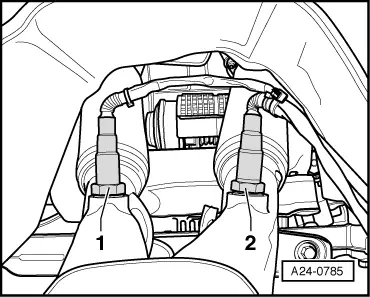
| 15 - | Ignition coils with output stages |
| q | Ignition coil 1 with output stage -N70- |
| q | Ignition coil 2 with output stage -N127- |
| q | Ignition coil 3 with output stage -N291- |
| q | Ignition coil 4 with output stage -N292- |
| 16 - | Fuel pressure sender -G247- |
| q | → Fig. |
| q | 15 Nm |
| 17 - | Variable intake manifold change-over valve -N156- |
| q | → Fig. |
| 18 - | Right-side of engine (in direction of travel) |
| q | → Fig. |
| q | Fuel pressure sender for low pressure -G410- (not fitted on engines with code letters BVZ and BVY) |
| q | Activated charcoal filter solenoid valve -N80- |
| q | Variable intake manifold change-over valve -N156- |
| q | 3-pin electrical connector for engine speed sender -G28- |
| q | Map-controlled engine cooling system thermostat -F265- |
| q | 3-pin connector for knock sensor 1 -G61- |
| q | Hall sender -G40- (camshaft position sensor) |
| 19 - | Hall sender -G40- (camshaft position sensor) |
| q | → Fig. |
| A - | Diagnostic connector |
| q | In driver's knee restraint |
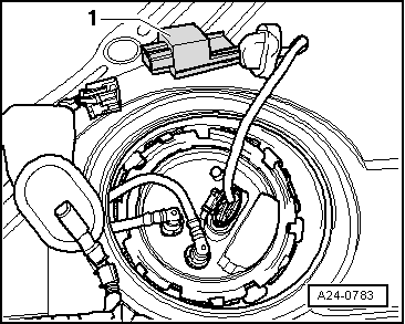
| B - | Fuel pump control unit -J538- |
| q | Adaption must be performed after renewing fuel pump control unit -J538-. Basic setting, measured value block 243, refer to → Rep. Gr.20 |
| q | Beneath rear seat bench → Fig. |
| C - | “EPC” warning lamp |
| q | In instrument cluster |
| D - | “MIL” exhaust emissions warning lamp |
| q | In instrument cluster |
| E - | Lambda probe -G39- and Lambda probe heater -Z19- |
| q | → Fig. |
| q | Removing and installing → Chapter |
| F - | Lambda probe 2 -G108- and Lambda probe heater 2 - Z28 - |
| q | Not fitted on engines with code letter BVZ |
| q | → Fig. |
| q | Removing and installing → Chapter |
| G - | Lambda probe, after catalytic converter -G130- and Lambda probe heater 1, after catalytic converter -Z29- |
| q | → Fig. |
| q | Removing and installing → Chapter |
| H - | Lambda probe 2, after catalytic converter -G131- and Lambda probe heater 2, after catalytic converter -Z30- |
| q | Not fitted on engines with code letters BLY, BHD, BMB and BVZ |
| q | → Fig. |
| q | Removing and installing → Chapter |
| I - | NOx sender -G295- and NOx sender heater -Z44- |
| q | → Fig. |
| q | Not fitted on engines with code letters BHD, BMB, BLY, BLR, BVZ and BVY |
| q | Removing and installing → Chapter |
| J - | Lambda probe 3 after catalytic converter -G287- and Lambda probe heater 3 after catalytic converter -Z64- |
| q | On engines with code letters BLR and BVY a Lambda probe 3 after catalytic converter -G287- is fitted in place of the NOx sender -G295-. |
| q | Removing and installing → Chapter |
| K - | Exhaust gas temperature sender 1 -G235- |
| q | → Fig. |
| q | Not fitted on engines with code letters BHD, BMB, BLY, BLR, BVZ and BVY |
| q | Removing and installing → Chapter |
| L - | NOx sensor control unit -J583- |
| q | → Fig. |
| q | Not fitted on engines with code letters BHD, BMB, BLY, BLR, BVZ and BVY |
| q | Removing and installing → Chapter |
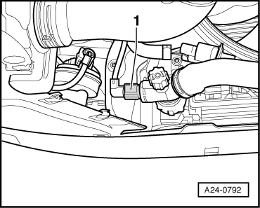
| M - | Brake light switch - F- and brake pedal switch -F63- |
| q | In footwell on brake pedal |
| q | → Fig. |
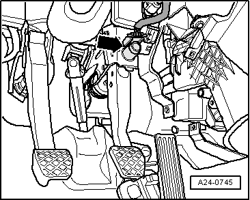
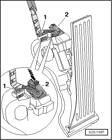
| N - | Accelerator position sender -G79- and accelerator position sender 2 -G185- |
| q | In footwell on accelerator pedal (both senders are accommodated in one housing) |
| q | → Fig. |
| O - | Clutch position sender -G476- |
| q | → Fig. |
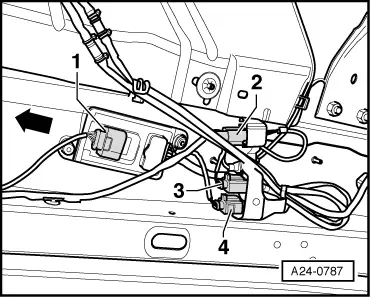
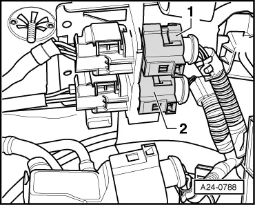
| P - | Motronic current supply relay -J271- |
| q | → Fig. |
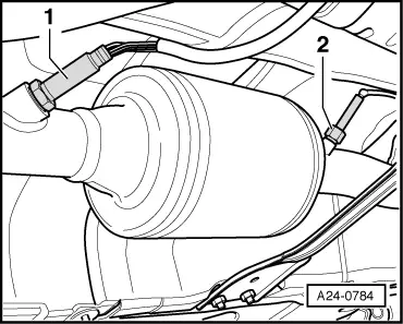
| Q - | Radiator fan control unit -J293- |
| q | Installed in left-side radiator fan (in direction of travel) |
| R - | Injectors |
| q | In fuel rail |
| q | Injector, cylinder 1 -N30- |
| q | Injector, cylinder 2 -N31- |
| q | Injector, cylinder 3 -N32- |
| q | Injector, cylinder 4 -N33- |
| The fuel injectors are high-pressure injectors. They inject fuel at high pressure (maximum approx. 110 bar) directly into the cylinder. |
| S - | 3-pin connector for knock sensor 2 -G66- |
| q | → Fig. |
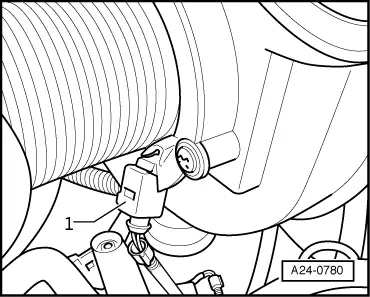
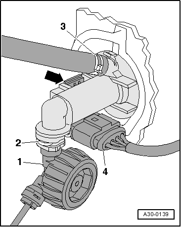
| T - | Oil pressure switch -F1- |
| q | → Fig. |
| V - | Engine speed sender -G28- |
| q | → Fig. |
| W - | Knock sensor 1 -G61- |
| q | → Fig. |
| q | Tightening torque: 20 Nm |
| X - | Knock sensor 2 -G66- |
| q | → Fig. |
| q | Tightening torque: 20 Nm |
| Y - | Intake manifold flap motor -V157- and intake manifold flap potentiometer -G336- |
| q | → Fig. |
| q | After the intake manifold has been renewed, intake manifold flap potentiometer -G336- must be adapted to engine control unit -J623-. For this purpose, use vehicle diagnosis and service information system -VAS 5052-, “Guided Functions”. |
|
|
|
|
 Note
Note
|
|
|
|
|
|
|
|
|
|
|
|
|
|
|
|
|
|
|
|
|
|
|
|
|
|
|
|
|
|
|
|
Note
|
|