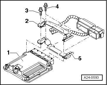
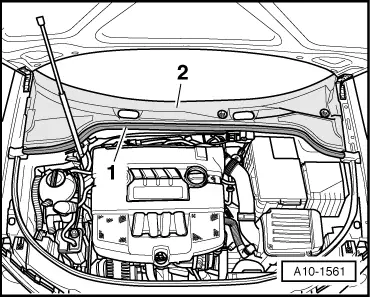
| The engine control unit -1- is bolted to the locking plates -2 and 5-. To make it more difficult to unscrew the shear bolts -4- for locking plate -2-, their threads have been coated with locking fluid. |
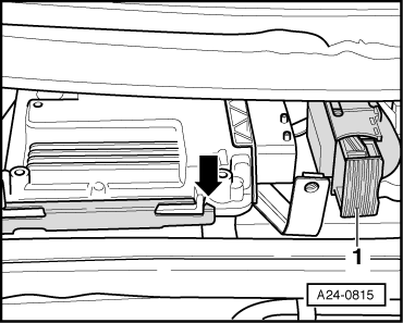
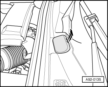
| The protective housing has to be removed before the connectors can be unplugged from the engine control unit (e.g. to connect the test box or renew the engine control unit). |
| To make it more difficult to unscrew the shear bolts, their threads have been coated with locking fluid. |
| –
| When renewing engine control unit, select diagnosis object “Replace engine control unit” in “Guided Functions” on vehicle diagnostic, testing and information system -VAS 5051B-. |
| –
| Switch off ignition and remove ignition key. |
| –
| Lever off caps on windscreen wiper arms with a screwdriver. |
|
|
|
 Note
Note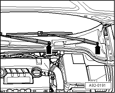
 WARNING