
A3 Mk2
| Fuel rail - exploded view |
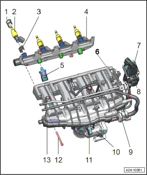
| 1 - | Radial compensation element |
| q | Renew if damaged |
| 2 - | Injector |
| q | With combustion chamber ring seal (teflon ring seal): always renew |
| q | Renew O-rings |
| q | Ensure correct installation position. |
| q | Removing and installing → Chapter |
| 3 - | Support ring |
| 4 - | Fuel rail |
| q | Removing and installing → Chapter |
| 5 - | Fuel pressure sender -G247- |
| q | 22 Nm |
| q | Tighten connecting piece to 30 Nm |
| 6 - | Fuel pressure sender for low pressure -G410- |
| 7 - | Fuel pressure regulating valve -N276- |
| 8 - | Mechanical single-plunger high-pressure pump |
| q | With fuel pressure regulating valve -N276- and fuel pressure sender, low pressure -G410- |
| q | An electric fuel pump (fitted in fuel tank) supplies fuel to the mechanical high-pressure pump at a pressure of approx. 6 bar. |
| q | When installing the high-pressure fuel pump, it is essential to ensure that no dirt enters the fuel system. |
| q | The fuel system must not be under pressure when installing the high-pressure pump; procedure for reducing fuel pressure → Chapter |
| q | Fuel pipes must be free of tension when installed. |
| q | Removing and installing → Chapter |
| 9 - | Activated charcoal filter solenoid valve 1 -N80- |
| 10 - | Throttle valve module -J338-, throttle valve drive for electric throttle -G186- |
| q | Throttle valve drive angle sender 1 for electric throttle -G187- and throttle valve drive angle sender 2 for electric throttle -G188- |
| q | After the throttle valve module -J338- has been renewed, it must be adapted to the engine control unit -J623-, see vehicle diagnostic and service information system -VAS 5052 A-“Guided Functions” |
| q | Removing and installing → Chapter |
| 11 - | Intake air temperature sender -G42- |
| q | 5 Nm |
| 12 - | Bolts for intake manifold |
| q | 9 Nm |
| 13 - | Intake manifold |
| q | Removing and installing → Chapter |