A3 Mk2
| Intake manifold (top section) - exploded view |
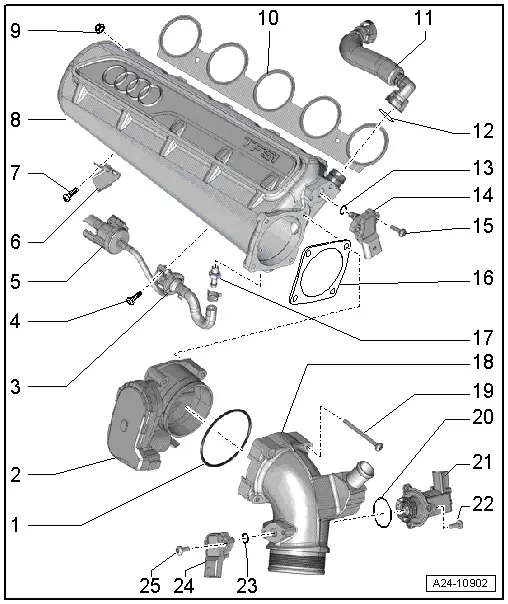
| 1 - | Seal |
| q | Renew |
| 2 - | Throttle valve module -J338- |
| q | Removing and installing → Chapter |
| q | After renewing, perform „Adaption“ in „Guided Functions“ |
| 3 - | Non-return valve |
| 4 - | Bolt |
| q | 9 Nm |
| 5 - | Activated charcoal filter solenoid valve 1 -N80- |
| 6 - | Bracket |
| 7 - | Bolt |
| q | 9 Nm |
| 8 - | Intake manifold (top section) |
| q | Removing and installing → Chapter |
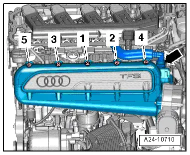
| 9 - | Nut |
| q | Tightening torque and sequence → Fig. |
| 10 - | Gasket |
| q | Renew |
| 11 - | Hose |
| q | For crankcase breather |
| 12 - | O-ring |
| q | Renew |
| 13 - | O-ring |
| q | Renew |
| 14 - | Intake air temperature sender -G42- / intake manifold pressure sender -G71- |
| q | Removing and installing → Chapter |
| 15 - | Bolt |
| q | 9 Nm |
| 16 - | Gasket |
| q | Renew |
| 17 - | Union |
| q | Apply locking fluid when installing; refer to → Electronic parts catalogue |
| q | 20 Nm |
| 18 - | Intake connecting pipe |
| 19 - | Bolt |
| q | 9 Nm |
| 20 - | O-ring |
| q | Renew |
| 21 - | Turbocharger air recirculation valve -N249- |
| q | Removing and installing → Rep. gr.21 |
| 22 - | Bolt |
| q | 9 Nm |
| 23 - | O-ring |
| q | Renew |
| 24 - | Charge pressure sender -G31- / intake air temperature sender 2 -G299- |
| q | Removing and installing → Rep. gr.21 |
| 25 - | Bolt |
| q | 9 Nm |