audi Workshop Repair Guides

Audi Workshop Service and Repair Manuals

Accelerator mechanism > < Checking fuel system for leaks - vehicles with unit injector engine
Checking for leaks
Checking for leaks
A leaking fuel system can cause:
t  Foam build-up or air bubbles in the supply line
t  Lack of power, misfiring
t  Starting problems
   
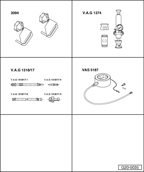
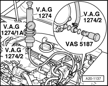
Special tools and workshop equipment required
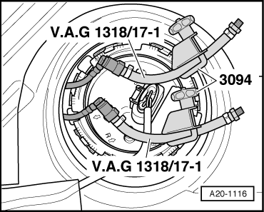
t  Hose clamps for hoses up to 25 mm -3094-
t  Cooling system tester -V.A.G 1274- with adapter -V.A.G 1274/1A- and adapter for testing diesel fuel -V.A.G 1274/2-
t  Adapter -V.A.G 1318/17-1- from adapter set -V.A.G 1318/17- (2 x)
t  Banjo bolt -VAS 5187/1A- from tandem pump tester -VAS 5187-

   
Procedure
Observe safety precautions → Chapter.
Observe rules for cleanliness → Chapter.
Engine cover panel (version 1):
–  Pull dipstick -1- out of guide tube.
–  Lift engine cover panel at the sides -arrows 2- and pull off towards the front -arrow 3-.
–  Re-insert dipstick in guide tube.
  A10-1664
Engine cover panel (version 2):
–  Lift off engine cover panel (outside -1- and inside -2-) by pulling up evenly.
  A10-10366
All vehicles (continued):
–  Pull cover off air duct (release clips on sides) -arrows-.
  A10-10367
–  Unclip air duct at the bottom by releasing clips -arrows-.
–  Detach air duct (bottom) together with air hose.
  A10-10368
–  Unplug electrical connector -1- at air mass meter -G70-.
–  Detach vent hose -3- and air hose -2-.
–  Unscrew bolt -4- and remove air cleaner housing.
  Note
Illustration shows vehicle with 2.0 litre engine.
  WARNING
t  The fuel system is pressurised. Wrap a cloth around the connection before opening the system. Then release pressure by carefully loosening the connection.
t  In extreme cases the temperature of the fuel lines and the fuel can be up to 100 °C after the engine is switched off. Allow the fuel to cool down before disconnecting the lines - danger of scalding.
t  Wear protective gloves.
t  Wear safety goggles.
  A10-10369
Vehicles with 2-valve engine:
–  Remove screw plug -arrow-.
  Note
Illustration shows tandem pump with engine removed from vehicle.
  N20-0288
Vehicles with 4-valve engine:
–  Remove screw plug -arrow-.
  Note
Illustration shows tandem pump with engine removed from vehicle.
  A20-1117
All vehicles (continued):
–  Attach adapter -V.A.G 1274/2- with adapter -V.A.G 1274/1A- to coolant system tester -V.A.G 1274-.
–  Connect adapter -V.A.G 1274/2- to tandem pump using banjo bolt -VAS 5187/1A-.
  A20-1137
–  Remove rear seat bench → Rep. gr.72.
–  Unclip retaining tabs -arrows- for flange cover.
  A20-1206
–  Disconnect fuel supply line -1- and fuel return line -2- by pressing release tabs.
  A20-1080
–  Connect one adapter -V.A.G 1318/17-1- onto supply line and one onto return line.
–  Clamp off adapters -V.A.G 1318/17-1- using hose clamps -3094-.
  Note
The hose clamps -3094- must not be applied directly to the fuel lines themselves as this can cause damage.
  A20-1116
–  Use cooling system tester -V.A.G 1274- to create a pressure of between 1.0 ... 1.5 bar.
–  If pressure drops constantly, locate leak and eliminate fault.
  Note
After removing pressure tester, tighten screw plug to 25 Nm. Renew seal.
  A20-1137

Accelerator mechanism > < Checking fuel system for leaks - vehicles with unit injector engine