
A3 Mk2
| Fuel tank with attached components - exploded view |
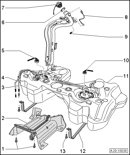
| 1 - | 26 Nm |
| 2 - | Heat shield for fuel tank |
| q | With support bracket |
| 3 - | Fuel supply line |
| q | Black |
| q | To fuel filter |
| q | Do not kink |
| q | Clip onto fuel tank |
| 4 - | Fuel return line |
| q | Blue |
| q | From fuel cooler |
| q | Do not kink |
| q | Clip onto fuel tank |
| 5 - | Electrical connector |
| q | For fuel system pressurisation pump -G6- and fuel gauge sender -G- |
| 6 - | Seal |
| q | Renew if damaged |
| 7 - | Filler cap |
| q | Secured to tank flap unit |
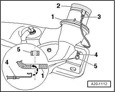
| 8 - | Earth connection |
| q | To eliminate electrostatic charge |
| q | Installation position → Fig. |
| q | Make sure connector is correctly seated and secure wire with flange bolt for fuel filler neck -item 9-. |
| q | After installation, use an ohmmeter to check the electrical connection between the metal ring on the fuel filler neck and a bare metal part on the body - Specification: approx. 0 ohms |
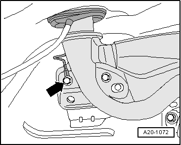
| 9 - | Flange bolt, 11 Nm |
| q | Secures fuel filler neck and earth connection -item 8- |
| 10 - | Electrical connector |
| q | For fuel gauge sender 2 -G169- |
| 11 - | Fuel tank |
| q | Removing and installing → Chapter |
| 12 - | Securing strap |
| q | Installation position: Fixing point (hole) points in direction of travel |
| 13 - | 26 Nm |
|
|
 Caution