audi Workshop Repair Guides

Audi Workshop Service and Repair Manuals

Fuel tank - USA vehicles (four-wheel drive) > < Draining fuel tank
Removing and installing fuel tank with attached components
Special tools and workshop equipment required
   
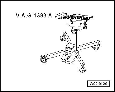
t  Engine and gearbox jack -V.A.G 1383 A-
Removing
Observe safety precautions → Chapter.
Observe rules for cleanliness → Chapter.
l  To reduce weight, the fuel tank must be empty when it is removed from the vehicle. Drain the tank if necessary. Procedure → Chapter.
  Caution
To prevent irreparable damage to the electronic components when disconnecting the battery:
Observe notes on procedure for disconnecting the battery.
–  Disconnect battery → Rep. gr.27.
  W00-0120
–  Remove rear seat bench → Rep. gr.72.
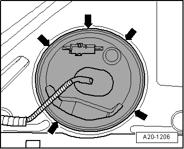
–  Unclip the retaining tabs -arrows- for the flange cover (right-side).
  A20-1206
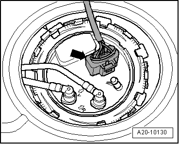
–  Unplug electrical connector -arrow- at flange.
  A20-10130
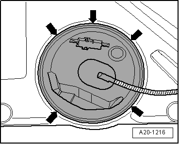
–  Unclip the retaining tabs -arrows- for the flange cover (left-side).
  A20-1216
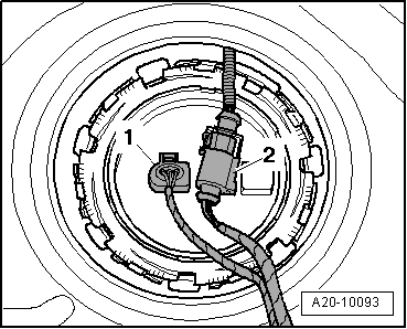
–  Unplug electrical connector -1- at flange.
–  Unplug electrical connector -2- for Haldex coupling.
  A20-10093
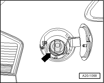
–  Open the tank flap.
–  Clean area around fuel filler neck.
–  Remove filler cap -arrow- from fuel filler neck.
–  Seal opening of fuel filler neck with a piece of clean foam or similar to prevent dirt from dropping into the tank.
  A20-1068
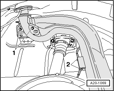
–  Remove rear right wheel housing liner → Rep. gr.66.
–  Unscrew bolts -1- for fuel filler neck.
–  Detach electrical wire -2- for ABS speed sensor from bracket on fuel filler neck.
  A20-1069
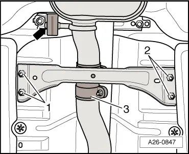
–  Remove rear cross member for underbody; to do so, unscrew nuts -1- and -2-.
  Caution
To protect flexible joints, secure front section of exhaust system to underbody with wire before you loosen bolt connections on clamp -3-.
–  Disconnect exhaust system at clamp -3-.
–  Unhook rear silencer at rubber mountings -arrow- and remove rear section of exhaust system.
  Note
A second person will be required for detaching rear section of exhaust system.
  A26-0847
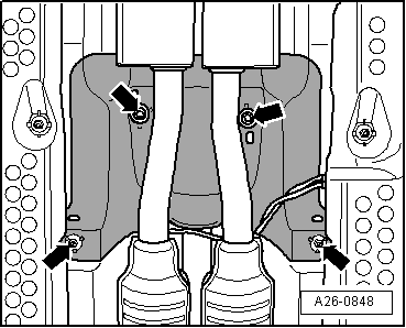
–  Remove heat shield for propshaft -arrows-.
–  Remove propshaft → Rep. gr.39.
  WARNING
Risk of injury - fuel system operates under high pressure.
To reduce the pressure in the fuel system, wrap a clean cloth around the connection and carefully loosen the connection.
  A26-0848
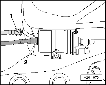
–  Disconnect fuel pipe -2- (black) and breather pipe -1- (white) at front right of fuel tank (press release tabs).
Vehicles with auxiliary heater:
–  In addition, disconnect fuel line leading to auxiliary heater at metering pump.
  A20-1070
All vehicles (continued):
  WARNING
To reduce weight, fuel tank must be empty upon removal.
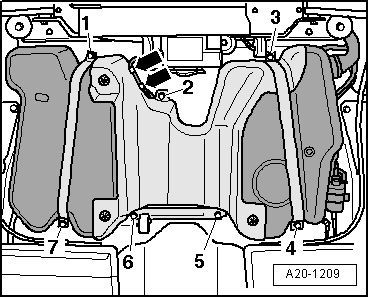
–  First remove bolts -2, 5- and -6-.
–  Disengage wiring harness -arrows- and move clear.
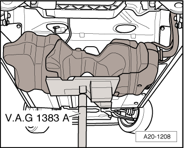
–  Position engine and gearbox jack -V.A.G 1383 A- below vehicle to support tank.
–  Unscrew bolts -1, 3, 4- and -7-.
  A20-1209
–  Then lower fuel tank using engine and gearbox jack -V.A.G 1383 A-, simultaneously guiding fuel tank down by hand.
–  Remove fuel tank downwards (turning it sideways as required).
–  In addition, a 2nd mechanic will be required to guide the fuel filler neck on trailing arm out by hand.
Installing
l  Tightening torques → Chapter
Installation is carried out in the reverse order; note the following:
  A20-1208
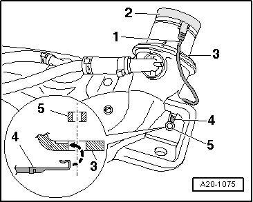
–  Check the earth wiring at both ends for traces of oxidation and remove oxidation if necessary.
–  Check installation position of earth connection:
l  Connector -1- must be seated securely on metal ring -2-.
l  Contact tab -4- must be attached to fuel tank -3- and secured with spacer bush -5-.
  A20-1075
–  Position fuel tank with securing straps on underbody, using engine and gearbox jack -V.A.G 1383 A-.
–  Attach wiring harness at top of fuel tank.
–  When installing fuel tank, make sure that the fuel filler neck is correctly inserted into the opening on the body.
  A20-1208
–  Secure fuel tank by first tightening bolts at points -1, 3, 4- and -7-, then at points -2, 5- and -6-.
  A20-1209
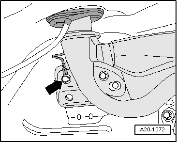
–  Secure contact tab for earth connection with securing bolt -arrow- for fuel filler neck.
  Caution
After installation, use an ohmmeter to check the electrical connection between the metal ring on the fuel filler neck and a bare metal part on the body:
Specification: approx. 0 Ohm
–  Attach electrical wire for ABS speed sensor to bracket on fuel filler neck.
–  Install rear right wheel housing liner → Rep. gr.66.
–  Install propshaft → Rep. gr.39.
–  Install rear section of exhaust system → Rep. gr.26.
–  Install rear seat bench → Rep. gr.72.
–  Connect battery. Observe notes on procedures required after connecting battery → Rep. gr.27.
  A20-1072

Fuel tank - USA vehicles (four-wheel drive) > < Draining fuel tank