
A3 Mk2
| Overview of fitting locations |
 Note
Note| For fitting location of clutch position sender -G476- on vehicles with manual gearbox, refer to → Fig.. |
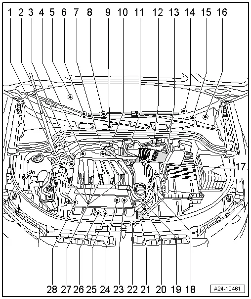
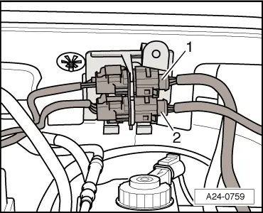
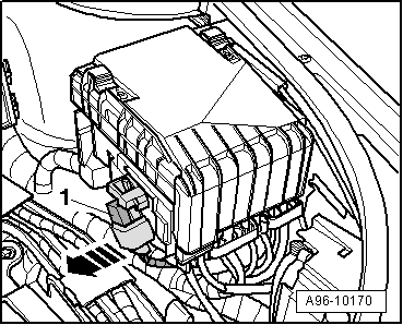
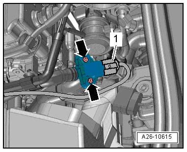
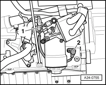
| 1 - | 3-pin connector |
| q | For knock sensor 1 -G61- |
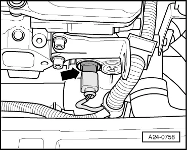
| 2 - | Knock sensor 1 -G61- |
| q | Fitting location → Fig. |
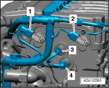
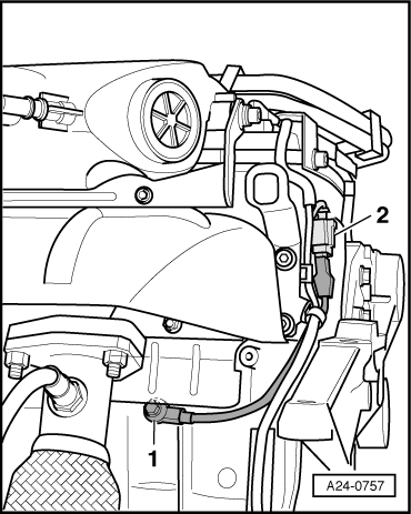
| 3 - | Activated charcoal filter solenoid valve 1 -N80- |
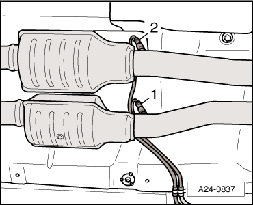
| 4 - | Lambda probe before catalytic converter -G39- with Lambda probe heater -Z19- |
| q | Fitting location → Fig. |
| q | Removing and installing → Chapter |
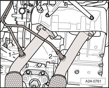
| 5 - | Connectors |
| q | For Lambda probe after catalytic converter -G130- with Lambda probe 1 heater after catalytic converter -Z29- and Lambda probe 2 after catalytic converter -G131- with Lambda probe 2 heater after catalytic converter -Z30- |
| q | Fitting location → Fig. |
| 6 - | Lambda probe after catalytic converter -G130- with Lambda probe 1 heater after catalytic converter -Z29- |
| q | Fitting location → Fig. |
| q | Removing and installing → Chapter |
| 7 - | Lambda probe 2 before catalytic converter -G108- with Lambda probe 2 heater -Z28- |
| q | Fitting location → Fig. |
| q | Removing and installing → Chapter |
| 8 - | Lambda probe 2 after catalytic converter -G131- with Lambda probe 2 heater after catalytic converter -Z30- |
| q | Fitting location → Fig. |
| q | Removing and installing → Chapter |
| 9 - | Motronic control unit -J220- |
| q | Removing and installing → Chapter |
| 10 - | Heating element for crankcase breather -N79- |
| 11 - | Throttle valve module -J338- |
| q | Including throttle valve drive for electric throttle -G186-, throttle valve drive angle sender 1 for electric throttle -G187- and throttle valve drive angle sender 2 for electric throttle -G188- |
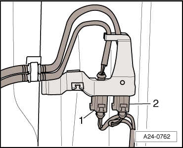
| 12 - | Connectors |
| q | For Lambda probe -G39- (before catalytic converter) with Lambda probe heater -Z19- and Lambda probe 2 -G108- (before catalytic converter) with Lambda probe 2 heater -Z28- |
| q | Fitting location → Fig. |
| 13 - | Air mass meter -G70- |
| 14 - | Instrument cluster |
| q | With exhaust emissions warning lamp -K83- |
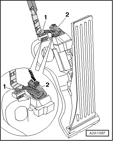
| 15 - | Accelerator position sender -G79- and accelerator position sender 2 -G185- |
| Fitting location → Fig. |
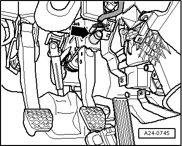
| 16 - | Brake light switch -F- and brake pedal switch -F47- |
| q | Fitting location → Fig. |
| 17 - | Sender 1 for secondary air pressure -G609- |
| q | Only for engine code CBRA |
| q | Fitting location → Fig. |
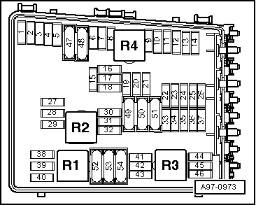
| 18 - | Secondary air pump relay -J299- |
| Fitting location → Fig. |
| 19 - | Motronic current supply relay -J271- |
| q | Fitting location → Fig. |
| 20 - | Fuel pump relay -J17- |
| q | Fitting location → Fig. |
| 21 - | Hall sender 2 -G163- |
| q | Fitting location → Fig. |
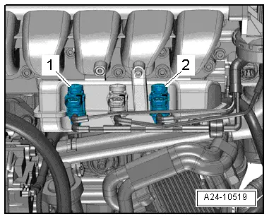
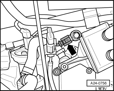
| 22 - | Exhaust camshaft control valve 1 -N318- |
| q | Brown connector |
| q | Fitting location → Fig. |
| 23 - | Inlet camshaft control valve 1 -N205- |
| q | Black connector |
| q | Fitting location → Fig. |
| 24 - | Hall sender -G40- |
| q | Fitting location → Fig. |
| 25 - | Coolant temperature sender -G62- |
| q | Fitting location → Fig. |
| 26 - | Engine speed sender -G28- |
| q | Fitting location → Fig. |
| 27 - | Actuator for intake manifold change-over |
| 28 - | Secondary air pump motor -V101- |
| 29 - | Variable intake manifold change-over valve -N156- |
| q | Fitting location → Fig. |
| 30 - | Secondary air inlet valve -N112- |
| q | For vehicles with vacuum-controlled combination valve for secondary air system |
| q | Vehicles with engine code CBRA also have secondary air inlet valve 2 -N320- |
| q | Fitting location → Fig. |
| 31 - | Knock sensor 2 -G66- |
| q | Fitting location → Fig. |
| 32 - | 3-pin connector |
| q | For engine speed sender -G28- |
| q | Fitting location → Fig. |
| 33 - | Ignition coils with output stages |
| q | Cylinder 1 ignition coil 1 with output stage -N70- |
| q | Cylinder 2 ignition coil 2 with output stage -N127- |
| q | Cylinder 3 ignition coil 3 with output stage -N291- |
| q | Cylinder 4 ignition coil 4 with output stage -N292- |
| q | Cylinder 5 ignition coil 5 with output stage -N323- |
| q | Cylinder 6 ignition coil 6 with output stage -N324- |
| 34 - | Injectors |
| q | Cylinder 1 injector for cylinder 1 -N30- |
| q | Cylinder 2 injector for cylinder 2 -N31- |
| q | Cylinder 3 injector for cylinder 3 -N32- |
| q | Cylinder 4 injector for cylinder 4 -N33- |
| q | Cylinder 5 injector for cylinder 5 -N83- |
| q | Cylinder 6 injector for cylinder 6 -N84- |
| q | Checking injection quantity and spray pattern; checking for leaks → Chapter |
| q | Removing and installing → Chapter |
|
|
|
|
|
|
|
|
|
|
|
|
|
|
|
|
|
|
Note
|
|
|
|
|
|
|
|
|
|
|
|
|
|
|
|