
A3 Mk2
| Removing and installing intake manifold |
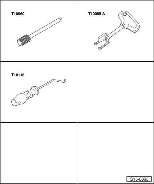
| Special tools and workshop equipment required |
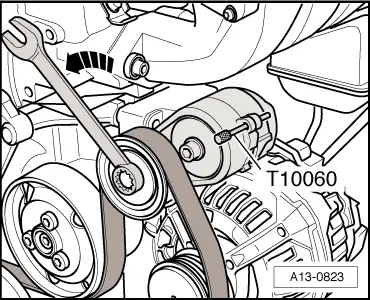
| t | Locking pin -T10060- |
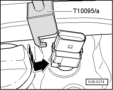
| t | Puller -T10095 A- |
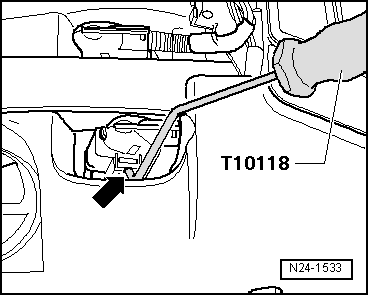
| t | Assembly tool -T10118- |
 Note
Note
|
 Caution
|
|
|
|
|
|
|
|
|
|
|
|
|
|
|
|
|
|
|
|
|
|
|
|
Note |
|
|
|
Note
|
|
|
|
Note |
|
|
|
|
|
|
|
|
|
 WARNING
Note
|
|
Note
|
|
Note
|
|
|
|
|
|
|
|
Note
|
|
Note
|
|
Note
|
|
| Component | Nm |
| Intake manifold to cylinder head | 13 |
| Intake manifold support to intake manifold | 20 |
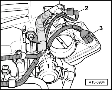
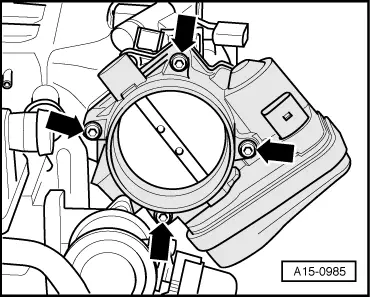
| Throttle valve module -J338- to intake manifold | 10 |
| Vacuum reservoir to intake manifold | 5 |
| Guide tube for oil dipstick to intake manifold | 5 |