audi Workshop Repair Guides

Audi Workshop Service and Repair Manuals

Ignition system, glow plug system > < Wiring and component check with adapter cable, 121-pinV.A.G 1598/31 (test box)
Renewing engine control unit
Removing
Special tools and workshop equipment required
   
t  Hot air blower -VAS 1978/14A--item 1- with shrink element for hot air blower -VAS 1978/15A--2- from wiring harness repair set -VAS 1978B-
t  Small mole grips -3-
  Note
When the connectors are unplugged from the engine control unit, the learnt values are erased, but the contents of the event memory remain intact.
–  When renewing engine control unit, select diagnosis object „Replace engine control unit“ in „Guided Functions“ mode of vehicle diagnostic tester.
–  Switch off ignition.
–  Lever off caps on windscreen wiper arms with a screwdriver.
  A24-0475
–  Loosen hexagon nuts -arrows- several turns.
–  Loosen wiper arms from wiper shafts by tilting them slightly.
–  Completely remove hexagon nuts and detach wiper arms from wiper shafts.
  A92-0191
–  Unclip washer jets -arrow-.
–  Push washer jets through assembly opening back into plenum chamber, leaving water hoses connected.
  A92-0135
–  Pull rubber seal -1- off plenum chamber cover.
–  Detach plenum chamber cover -2-.
  A10-1561
Bracket for engine control unit: version 1
  A24-0815
Bracket for engine control unit: version 2
–  Release clip »arrow« and remove engine control unit. You can then unplug connectors from engine control unit.
The following steps are only required if the engine control unit is installed as in version 1 in the illustration.
Run wiper shafts to service position.
–  First close bonnet.
–  Switch ignition on and then off again. Within 10 seconds, press wiper switch down once to brief wipe position.
  Note
The wiper shafts will now run to the service position.
–  Then open bonnet again.
–  Remove ignition key.
Work steps for vehicles up to approx. 08.2005 only
  A24-10451
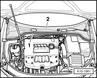
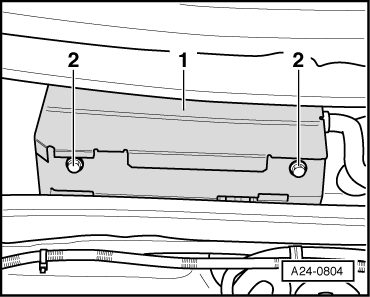
To make it more difficult to access the connectors on the engine control unit, the control unit is covered by a protective housing -1- and secured with shear bolts -2-.
To make it more difficult to unscrew the shear bolts, their threads have been coated with locking fluid.
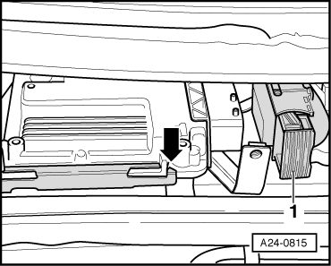
Engine control unit must be separated from protective housing before connectors can be unplugged from engine control unit (e.g. when connecting test box or replacing engine control unit). This procedure is described in the following.
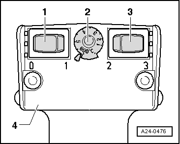
Procedure:
  WARNING
The following procedure must be followed exactly to prevent any damage (scorching) to wiring, connectors, insulation and control units. Observe operating instructions for hot air blower.
  A24-0804
–  Select settings on hot air blower as shown in illustration, i.e. set temperature potentiometer -2- to maximum heat output and two-stage air flow switch -3- to position 3.
  Note
t  Then use hot air blower to heat shear bolts. This step reduces inhibiting action of locking fluid on shear bolt threads and makes it easier to unscrew these bolts.
t  Cover up all painted parts to avoid any damage caused by hot air blower or vice-grip pliers.
  WARNING
Parts of the protective housing will become very hot as a result of heating the shear bolts. Take care to avoid burns. Try to ensure that only the shear bolt is heated and none of the nearby components. These should be covered if necessary.
–  Place the hot air blower nozzle close to the shear bolt on the protective housing.
–  Switch on the hot air blower and heat the bolt for approximately 20 to 25 seconds.
–  Then grasp the bolt head with the vice-grip pliers and unscrew the shear bolt.
The procedure for the second shear bolt is exactly the same.
Engine control unit can now be separated from protective housing.
  A24-0476
–  Release front connector -1- from engine control unit and unplug connector.
–  Pull engine control unit out of retainer -arrow- (wiper shafts in service position).
–  Release rear connector on engine control unit and unplug connector.
Installing engine control unit on vehicles with protective housing
Installation is performed in the reverse sequence.
–  Make sure you fit protective housing back on engine control unit.
–  Clean threaded holes for shear bolts to remove any residue from locking fluid. This can be done using a thread tap.
–  Always use new shear bolts.
–  Return wiper arms to normal position.
–  First close bonnet.
–  Switch on ignition and press wiper switch down once to brief wipe position. The wipers will then return to the normal position.
The following step must be performed after installing the new engine control unit:
–  Activate engine control unit via a vehicle diagnostic tester in „Guided Functions“ mode, „Replace engine control unit“.
  A24-0815

Ignition system, glow plug system > < Wiring and component check with adapter cable, 121-pinV.A.G 1598/31 (test box)