audi Workshop Repair Guides

Audi Workshop Service and Repair Manuals

Bleeding fuel system without return pipe > < Checking fuel pressure regulator and residual pressure
Checking for leaks, checking injection quantity and spray pattern of injectors
Special tools and workshop equipment required
t  Remote control for V.A.G 1348 -V.A.G 1348/3A-
t  Auxiliary measuring set -V.A.G 1594C-
   
t  Injection rate tester -V.A.G 1602-
  W24-10005
t  Adapter cable, 121-pin -V.A.G 1598/31- (test box)
Checking for leaks
  Note
Fuel pressure OK; checking → Chapter.
–  Remove fuel rail with injectors installed from intake manifold. Fuel hoses remain connected → Chapter.
–  Connect test box -V.A.G 1598/31- to wiring harness for engine control unit. Do not connect engine control unit → Chapter.
–  Bridge contacts 1 and 80 on the test box using test leads from auxiliary measuring set -V.A.G 1594C-. (This creates an earth connection to one side of the fuel pump relay coil.)
–  Switch on ignition.
  Note
Once the ignition has been switched on the fuel pump runs continuously, even if the engine is not running. This is because the fuel pump relay receives a positive voltage supply via the central electrics when the ignition is switched on. The earth connection for the fuel pump relay is set up via the test lead bridge connection in the test box.
–  Visually check the fuel injectors for leaks.
t  When the fuel pump is running, no more than 1 to 2 drops a minute should escape from any one of the injectors.
–  If the fuel loss is greater, switch off the fuel pump (turn off ignition) and renew the faulty injector → Chapter.
Checking injection quantity
  Note
Make sure contacts 1 and 80 on test box remain bridged. (This creates an earth connection to one side of the fuel pump relay coil.)
–  Place the injector which is to be tested into measuring glass of injection rate tester -V.A.G 1602-.
  W00-0943
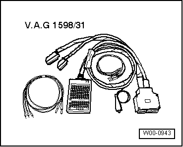
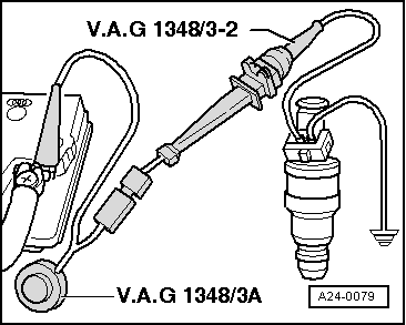
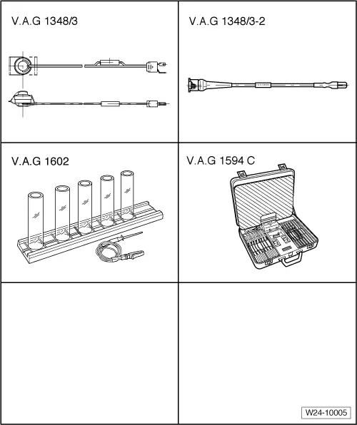
–  Connect one of the injector contacts to engine earth using test lead and crocodile clip from auxiliary measuring set -V.A.G 1594C-.
–  Connect second injector contact to positive using remote control for V.A.G 1348 -V.A.G 1348/3A-, adapter lead -V.A.G 1348/3-2- and test lead.
–  Switch on ignition.
t  The fuel pump should run.
–  Operate remote control for V.A.G 1348 -V.A.G 1348/3A- for 30 seconds.
–  Perform measurements on all injectors.
–  Once all four injectors have been actuated, place measuring glasses on a level surface.
t  Specification: 85...105 ml for each injector
–  When checking the injection quantity, also check the spray pattern. The spray pattern should be the same for all injectors.
–  If the measured value for one or more of the injectors is outside the tolerance range, switch off the fuel pump (switch off ignition) and renew the defective injector.
–  Install injectors together with fuel rail → Chapter.
  A24-0079

Bleeding fuel system without return pipe > < Checking fuel pressure regulator and residual pressure