
A3 Mk2
 Note
Note
|
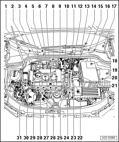
| 1 - | Intake manifold flap motor -V157- |
| q | Removing and installing → Chapter |
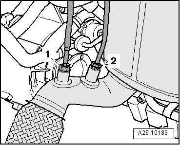
| 2 - | Temperature sender after particulate filter -G527- |
| q | Fitting location → Fig. |
| q | Removing and installing → Rep. Gr.26 |
| 3 - | Lambda probe -G39- with Lambda probe heater -Z19- |
| q | Fitting location → Fig. |
| q | Removing and installing → Chapter |
| 4 - | Exhaust gas recirculation valve -N18- with exhaust gas recirculation potentiometer -G212- |
| q | Fitting location → Fig. |
| q | Removing and installing → Rep. Gr.26 |
| 5 - | Engine control unit |
| q | Removing and installing → Chapter |
| 6 - | Temperature sender before particulate filter -G506- |
| q | Fitting location → Fig. |
| q | Removing and installing → Rep. Gr.26 |
| 7 - | Exhaust gas pressure sensor 1 -G450- |
| q | Fitting location → Fig. |
| q | Removing and installing → Chapter |
| 8 - | Exhaust gas temperature sender 1 -G235- |
| q | Fitting location → Fig. |
| q | Removing and installing → Rep. Gr.26 |
| 9 - | Unit injectors |
| q | Unit injector solenoid valve, No. 1 cyl. -N240- |
| q | Unit injector solenoid valve, No. 2 cyl. -N241- |
| q | Unit injector solenoid valve, No. 3 cyl. -N242- |
| q | Unit injector solenoid valve, No. 4 cyl. -N243- |
| q | Removing and installing → Chapter |
| 10 - | Exhaust gas recirculation cooler change-over valve -N345- |
| q | Fitting location → Fig. |
| 11 - | Coolant temperature sender -G62- |
| q | Fitting location → Fig. |
| q | If necessary release pressure in cooling system before removing |
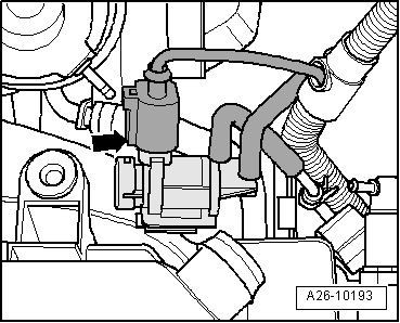
| 12 - | Charge pressure control solenoid valve -N75- |
| q | Fitting location → Fig. |
| 13 - | Electrical connectors on left side of bulkhead |
| q | Fitting location → Fig. |
| 14 - | Engine electronics warning lamp -K149- |
| q | In instrument cluster |
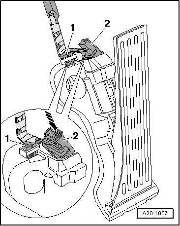
| 15 - | Accelerator position sender -G79- with accelerator position sender 2 -G185- |
| q | Fitting location → Fig. |
| q | Removing and installing → Rep. Gr.20 |
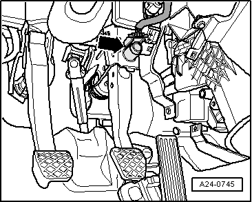
| 16 - | Brake light switch -F- and brake pedal switch -F63- |
| q | Fitting location → Fig. |
| q | Removing and installing → Rep. Gr.46 |
| 17 - | Fuel pump relay -J17- |
| q | Fitting location → Fig. |
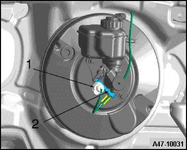
| 18 - | Clutch position sender -G476- |
| q | Fitting location → Fig. |
| q | Removing and installing → Rep. Gr.30 |
| 19 - | Relay and fuse holder in electronics box in engine compartment |
| q | With terminal 30 voltage supply relay -J317- |
| q | With terminal 15 voltage supply relay -J329- |
| q | For identification of socket position refer to → Current flow diagrams, Electrical fault finding and Fitting locations |
| 20 - | Automatic glow period control unit -J179- |
| q | Under electronics box in engine compartment |
| q | Fitting location → Fig. |
| q | Removing and installing → Chapter |
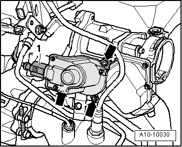
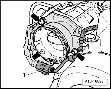
| 21 - | Air mass meter -G70- |
| q | Removing and installing → Chapter |
| 22 - | Tandem pump |
| q | Removing, installing and checking → Rep. Gr.20 |
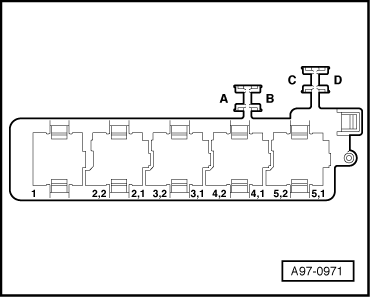
| 23 - | Multi-pin connector |
| q | For unit injectors |
| q | Fitting location → Fig. |
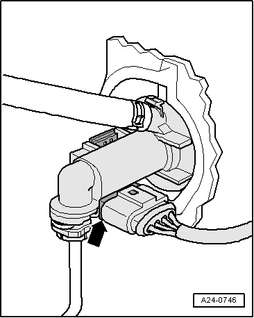
| 24 - | Engine speed sender -G28- |
| q | Fitting location → Fig. |
| q | Removing and installing → Chapter |
| q | 4.5 Nm |
| 25 - | Fuel temperature sender -G81- |
| q | Fitting location → Fig. |
| 26 - | Glow plugs |
| q | Glow plug 3 -Q12- |
| q | Glow plug 4 -Q13- |
| q | Removing and installing ceramic glow plugs → Chapter |
| 27 - | 3-pin connector |
| q | For Hall sender -G40- |
| q | Fitting location → Fig. |
| 28 - | Radiator outlet coolant temperature sender -G83- |
| q | Fitting location → Fig. |
| 29 - | Glow plugs |
| q | Glow plug 1 -Q10- |
| q | Glow plug 2 -Q11- |
| q | Removing and installing ceramic glow plugs → Chapter |
| 30 - | Charge pressure sender -G31- with intake air temperature sender -G42- |
| q | Fitting location → Fig. |
| 31 - | Hall sender -G40- |
| q | For camshaft position |
| q | Fitting location → Fig. |
|
|
|
|
Note
|
|
|
|
|
|
|
|
|
|
|
|
|
|
Note
|
|
|
|
|

|
Note
|
|
Note
|
|
|
|
|
|
|
|
|
|
|
|
|
|
|
|
|
|