audi Workshop Repair Guides

Audi Workshop Service and Repair Manuals

Removing and installing Lambda probe G39 with Lambda probe heater Z19 > < Wiring and component check with test box V.A.G 1598/42
Removing and installing engine control unit
  Note
   
t  The engine control unit is bolted to its protective housing. To make it more difficult to unscrew the shear bolts -arrows-, their threads have additionally been coated with locking fluid.
t  The protective housing has to be removed before the connectors can be unplugged from the engine control unit (e.g. to connect the test box or renew the engine control unit).
Special tools and workshop equipment required
  A24-0748
t  Hot air blower -1- from the wiring harness repair set -VAS 1978-
t  Nozzle attachment -2- from the wiring harness repair set -VAS 1978-
t  Vice-grip pliers -3- (commercially available)
Removing
–  When renewing engine control unit, select diagnosis object “Renew engine control unit” in “Guided Fault Finding” → Vehicle diagnosis, testing and information system VAS 5051.
–  With bonnet closed, move windscreen wipers to service position (switch ignition on and off again briefly).
–  Within 10 seconds, press wiper switch down once to “brief wipe” position.
l  The wipers will now run onto the main part of the windscreen (service position).
–  Remove ignition key.
–  Open bonnet and lever off caps from windscreen wiper arms with a screwdriver.
–  Loosen hexagon nuts several turns.
–  Loosen wiper arms from wiper shafts by tilting slightly, remove nuts completely and take off wiper arms.
  A24-0475
–  Unclip washer jets -arrow-.
–  Push washer jet through assembly opening back into plenum chamber, leaving hoses connected.
  A92-0135
–  Pull off rubber seal -1- on plenum chamber cover.
–  Detach plenum chamber cover -2-.
  Caution
The following procedure must be followed exactly to prevent any damage (burning) to wiring, connectors, insulation and control units. Observe operating instructions for hot air blower.
  A10-1561
–  Select settings on hot-air blower as shown in illustration, i.e. set temperature potentiometer -2- to maximum heat output and two-stage air flow switch -3- to position “3”.
  Note
t  Then use hot air blower to heat threaded holes in protective housing into which shear bolts have been screwed. This reduces the inhibiting action of the locking fluid on the shear bolt threads and makes it easier to unscrew these bolts.
t  Cover up all painted parts to avoid any damage caused by hot air blower or vice-grip pliers.
  WARNING
Parts of the protective housing will become very hot as a result of heating the shear bolts. Take care to avoid burns. Try to ensure that only the thread is heated and none of the nearby components. These should be covered if necessary.
  A24-0476
–  Carry out the following operations on the two shear bolts -arrows-, one after the other.
–  Place the nozzle of the hot air blower close to the shear bolt on the protective housing.
–  Switch on the hot air blower and heat the bolt for approximately 20 ... 25 seconds.
–  Then grasp the bolt head with the vice-grip pliers and unscrew the shear bolt.
–  Take off the protective housing.
  A24-0748
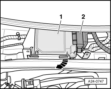
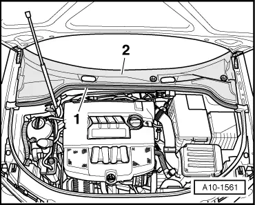
–  Release and unplug front connector -2- on engine control unit.
–  Release retaining clip -arrow-.
–  Pull engine control unit -1- out of bracket.
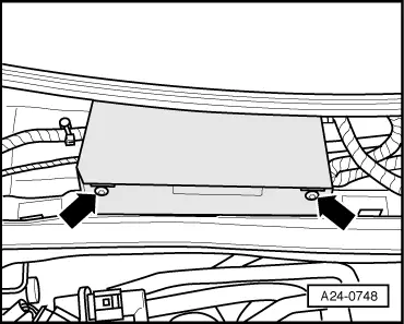
–  Release and unplug rear connector on engine control unit.
  Note
When the engine control unit is disconnected, the learnt values are erased but the contents of the fault memory remain intact.
Installing
Installation is carried out in the reverse order; note the following:
–  Protective housing must be fitted back on engine control unit.
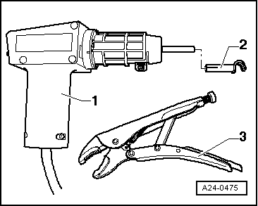
–  Clean threaded holes for shear bolts to remove any residue from locking fluid. This can be done using a thread tap.
–  Use new shear bolts.
–  With bonnet closed, move windscreen wiper motor back to normal park position (switch ignition on and off again briefly).
–  Within 10 seconds, press wiper switch down once to “brief wipe” position.
l  The wiper motor will run back to the normal park position.
–  Install windscreen wiper arms → Rep. Gr.92.
After installing a new engine control unit, the following operations must be performed:
–  Activate engine control unit in “Guided Fault Finding” under diagnosis option “Replace engine control unit” → Vehicle diagnosis, testing and information system VAS 5051.
  A24-0747

Removing and installing Lambda probe G39 with Lambda probe heater Z19 > < Wiring and component check with test box V.A.G 1598/42