
A3 Mk2
|
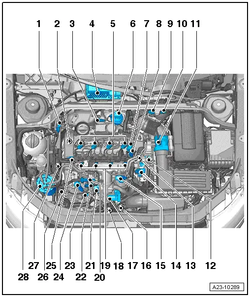
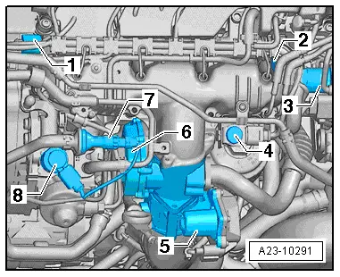
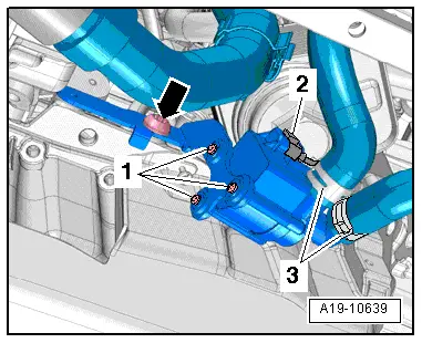
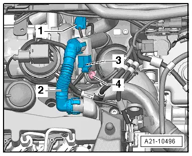
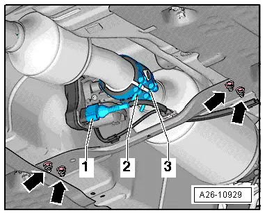
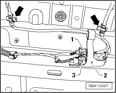
| 1 - | Pressure sensor |
| q | On vehicles with engine codes CBAA, CBAB and CBBB, the component's designation is exhaust gas pressure sensor 1 -G450- |
| q | Removing and installing → Chapter |
| q | On vehicles with engine code CBEA, the component's designation is pressure differential sender -G505- |
| q | Removing and installing → Chapter |
| q | Fitting location → Fig. |
| q | Adaption must be performed after renewing this component |
| 2 - | Hall sender -G40- |
| q | Fitting location → Fig. |
| q | Removing and installing → Chapter |
| q | 10 Nm |
| 3 - | Lambda probe -G39- with Lambda probe heater -Z19- |
| q | Fitting location → Fig. |
| q | Removing and installing → Chapter |
| q | Removing and installing (CBEA) → Chapter |
| q | 50 Nm |
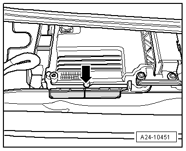
| 4 - | Engine control unit -J623- |
| q | Fitting location → Fig. |
| q | Removing and installing → Chapter |
| 5 - | Injectors |
| q | Fitting location → Fig. |
| q | Removing and installing → Chapter |
| 6 - | Position sender for charge pressure positioner -G581- |
| q | Fitting location → Fig. |
| 7 - | Pressure retention valve |
| q | The pressure retention valve maintains a residual pressure of approx. 10 bar in the return lines |
| q | This residual pressure is required for the control function of the injectors |
| q | The pressure retention valve may only be renewed together with the fuel return lines |
| q | After replacement, engine must be run at idling speed for approx. 2 minutes to bleed fuel system |
| q | Checking pressure retention valve → Chapter |
| 8 - | Fuel pressure regulating valve -N276- |
| q | Fitting location → Fig. |
| q | Checking → Chapter |
| q | Removing and installing → Chapter |
| q | 80 Nm |
| 9 - | Charge pressure control solenoid valve -N75- |
| q | Fitting location → Fig. |
| q | Electrical connector for exhaust gas temperature sender 3 -G495- |
| 10 - | Electrical connector |
| q | For exhaust gas temperature sender 4 -G648- |
| q | For exhaust gas temperature sender 1 -G235- |
| q | For Lambda probe -G39- |
| q | Fitting location → Fig. |
| 11 - | Air mass meter -G70- |
| q | Removing and installing → Chapter |
| 12 - | Coolant temperature sender -G62- |
| q | Fitting location → Fig. |
| q | Removing and installing → Rep. gr.19 |
| 13 - | Engine speed sender -G28- |
| q | Fitting location → Fig. |
| q | 4.5 Nm |
| 14 - | Component on intake manifold |
| q | Variable intake manifold motor -V183- with variable intake manifold position sender -G513- (engine codes CBAA, CBAB, CBBB) |
| q | Intake manifold flap motor -V157- with intake manifold flap potentiometer -G336- (engine code CBEA) |
| q | Fitting location → Fig. |
| 15 - | Exhaust gas recirculation cooler change-over valve -N345- |
| q | Engine codes CBAA, CBAB, CBBB only |
| q | Fitting location → Fig. |
| 16 - | Pump for exhaust gas recirculation cooler -V400- |
| q | Fitting location → Fig. |
| 17 - | Component on intake manifold |
| q | Intake manifold flap motor -V157- with intake manifold flap potentiometer -G336- (engine codes CBAA, CBAB, CBBB) |
| q | Throttle valve module -J338- with throttle valve potentiometer -G69- (engine code CBEA) |
| q | Fitting location → Fig. |
| q | Intake manifold - exploded view → Chapter |
| q | Removing and installing → Chapter |
| 18 - | Charge pressure sender -G31- |
| q | Combined with intake air temperature sender -G42- |
| q | Fitting location → Fig. |
| q | Removing and installing → Rep. gr.21 |
| 19 - | Glow plugs |
| q | Glow plug 1 -Q10- |
| q | Glow plug 2 -Q11- |
| q | Glow plug 3 -Q12- |
| q | Glow plug 4 -Q13- |
| q | Removing and installing → Chapter |
| 20 - | Fuel temperature sender -G81- in fuel supply line |
| q | Fitting location → Fig. |
| 21 - | Exhaust gas recirculation |
| q | Exhaust gas recirculation valve -N18- with exhaust gas recirculation potentiometer -G212- (engine codes CBAA, CBAB, CBBB only) |
| q | Exhaust gas recirculation control motor -V338- with exhaust gas recirculation potentiometer -G212- (engine code CBEA only) |
| q | Fitting location → Fig. |
| 22 - | Fuel return line connection to fuel filter |
| 23 - | Fuel supply line connection (high-pressure pipe) to fuel rail (high-pressure reservoir) |
| 24 - | High-pressure fuel pump with fuel metering valve -N290- |
| q | Do not open fuel metering valve -N290- |
| q | After renewing, first fuel filling MUST be performed (it is important not to allow pump to run while it is still empty) → Chapter |
| q | Removing and installing → Chapter |
| 25 - | Fuel pressure sender -G247- |
| q | Fitting location → Fig. |
| q | Removing and installing → Chapter |
| q | 100 Nm |
| 26 - | Radiator outlet coolant temperature sender -G83- |
| q | Fitting location (engine codes CBAA, CBAB, CBBB only) → Fig. |
| q | Fitting location (engine code CBEA only) → Fig. |
| q | Removing and installing → Rep. gr.19 |
| 27 - | Supplementary fuel pump -V393- |
| 28 - | Fuel filter |
| q | Fuel filter - exploded view → Rep. gr.20 |
| q | Renewing fuel filter → Rep. gr.20 |
| A - | Low heat output relay -J359- and high heat output relay -J360- |
| q | Fitting location → Current flow diagrams, Electrical fault finding and Fitting locations |
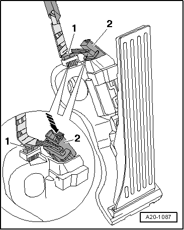
| B - | Brake light switch -F- and brake pedal switch -F47- |
| q | Fitting location → Fig. |
| q | In footwell on brake pedal |
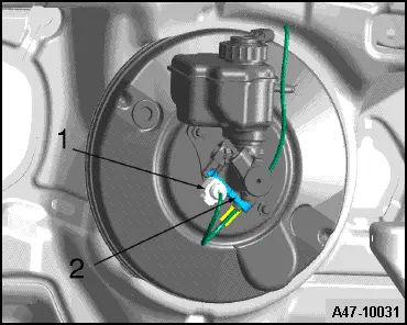
| C - | Clutch position sender -G476- |
| q | Fitting location → Fig. |
| q | Only fitted on vehicles with manual gearbox |
| D - | Accelerator position sender -G79- and accelerator position sender 2 -G185- |
| q | Fitting location → Fig. |
| q | Removing and installing → Rep. gr.20 |
| E - | Exhaust gas recirculation temperature sensor -G98- (engine code CBEA only) |
| q | Is screwed into housing for exhaust gas recirculation |
| q | Electrical connector → Fig. |
| q | Removing and installing → Rep. gr.26 |
| F - | Exhaust gas recirculation control motor -V338- with exhaust gas recirculation potentiometer 2 -G466- (engine code CBEA only) |
| q | Is screwed into housing for exhaust gas recirculation |
| q | Removing and installing → Rep. gr.26 |
| G - | Exhaust gas pressure sensor 1 -G450- (engine code CBEA only) |
| q | Fitting location → Fig. |
| q | Removing and installing → Chapter |
| H - | Exhaust gas temperature sender 1 -G235- |
| q | Fitting location → Fig. |
| q | Lambda probes and exhaust gas temperature sensors - exploded view → Chapter |
| q | Removing and installing → Rep. gr.26 |
| I - | Exhaust gas temperature sender 2 -G448- (engine code CBEA only) |
| q | Fitting location → Fig. |
| q | Fitting location of electrical connector → Fig. |
| q | Lambda probes and exhaust gas temperature sensors - exploded view → Chapter |
| q | Removing and installing → Rep. gr.26 |
| J - | Exhaust gas temperature sender 3 -G495- |
| q | Fitting location → Fig. |
| q | Lambda probes and exhaust gas temperature sensors - exploded view → Chapter |
| q | Removing and installing → Rep. gr.26 |
| K - | Exhaust gas temperature sender 4 -G648- |
| q | Fitting location → Fig. |
| q | Lambda probes and exhaust gas temperature sensors - exploded view → Chapter |
| q | Removing and installing → Rep. gr.26 |
| L - | Lambda probe after catalytic converter -G130- (engine code CBEA only) |
| q | Fitting location of electrical connector → Fig. |
| q | Fitting location → Fig. |
| q | Removing and installing → Chapter |
| M - | Exhaust flap control unit -J883- (engine code CBEA only) |
| q | Fitting location → Fig. |
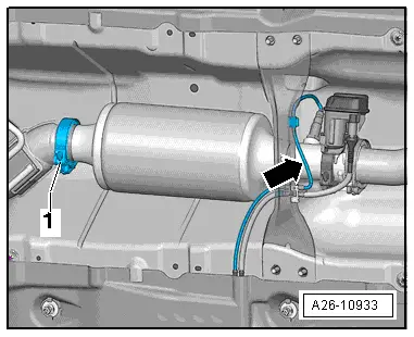
| N - | Particulate filter |
| q | Fitted on underbody |
| q | Combined with a catalytic converter |
| q | Adaption must be performed after renewing this component |
| q | Removing and installing → Rep. gr.26 |
|
|
 Note
Note
|
|
|
|
|
|
|
|
|
|
|
|
|
|
|
|
|
|
|
|
|
|
|
|
|
|
|
|
|
|
|
|
|
|
|
|
|
|
|
|
|
|
|
|
|
|
|
|
|
|
|
|