audi Workshop Repair Guides

Audi Workshop Service and Repair Manuals

Rear suspension, drive shaft > < Servicing drive shaft with triple roller joint AAR 2600i (version with splines on inner joint) and AAR 3300i (version with inter
Dismantling and assembling drive shaft with triple roller joint AAR 2600i (version with splines on inner joint) and AAR 3300i (version with internal splines on inner joint)
   
Dismantling and assembling drive shaft with triple roller joint AAR 2600i (version with splines on inner joint) and AAR 3300i (version with internal splines on inner joint)
Special tools and workshop equipment required
t  Thrust plate -VW 401-
t  Thrust plate -VW 402-
t  Press tool -VW 408 A-
t  Press tool -VW 411-
t  Tube -VW 416 B-
t  Thrust plate -VW 447 H-
t  Assembly tool -T10065-

  W00-1070
Dismantling
–  Open hose clip on shaft and push back boot.
–  Pull joint body off drive shaft.
–  Remove circlip.
1 - Pliers (commercial type) or -VW 161 A-
–  Insert drive shaft in press.
  N40-0185
–  Press triple roller spider off drive shaft.
–  Pull boot off drive shaft.
–  Clean shaft, joint body and groove for seal.
  N40-0444
Assembling
–  Push small hose clip for boot onto shaft.
–  Slide boot onto shaft.
–  Grease splines -A- on drive shaft lightly with grease used in joint before fitting triple roller spider onto drive shaft.
  A42-10049
Fitting triple roller spider (tapered drive shaft version):
t  Chamfer on spider faces towards shaft and is used as an assembly aid.
–  Fit triple roller spider on shaft and press on as far as stop.
  N40-0445
Fitting triple roller spider (cylindrical drive shaft version):
–  Fit triple roller spider on shaft and press on as far as stop.
Both drive shaft versions (continued):
–  Make sure pressure does not exceed 3.0 t.
–  If necessary, coat splines of drive shaft and triple roller spider with polycarbamide grease G 052 142 A2.
–  Install circlip (ensure proper seating).
–  Slide joint body over rollers and hold in position.
–  Press 70 g of drive shaft grease from repair kit into triple roller joint.
–  Press 70 g of drive shaft grease from repair kit into boot.
–  Install joint boot.
–  Install hose clip.
Checking outer constant velocity joint
The joint should be dismantled to renew dirty grease or for checking the balls and ball races for wear and damage.
Removing
  N40-0446
–  Before dismantling, mark position of ball hub in relation to ball cage and joint body with an electric scriber or oil stone -arrow-.
–  Swivel ball hub and ball cage and take out balls one after the other.
  A40-0172
–  Turn cage until two cage openings -arrow- are level with joint body.
–  Lift out cage together with hub.
  A40-0155
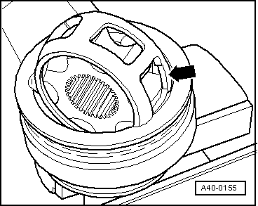
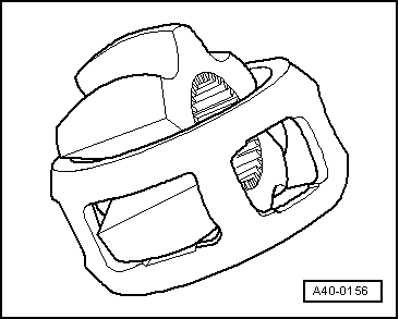
–  Swivel one segment of the hub into one of the cage openings.
–  Pivot hub out of cage.
  Note
t  The 6 balls in each joint belong to one tolerance group. Check stub axle, hub, cage and balls for pitting and signs of seizure.
t  Excessive backlash in the joint will cause knocking or jolts under load change; in such cases the joint must be renewed.
t  Polished areas and visible tracks in the ball races do not justify renewal of the joint.
Installing
Installation is performed in reverse sequence; note the following:
–  Pack required amount of grease into joint body (check table).
t  Grease quantity for outer joint (90 mm dia.) → Anchor
t  Grease quantity for outer joint (98 mm dia.) → Anchor
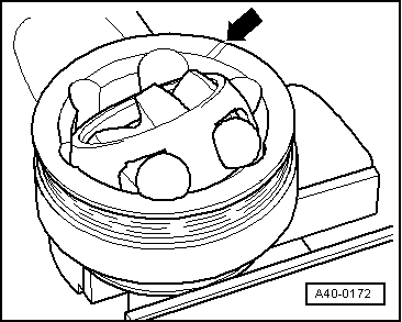
–  Fit cage with hub into joint body.
  Note
Make sure cage is inserted in correct position (i.e. sides facing in same direction as original position).
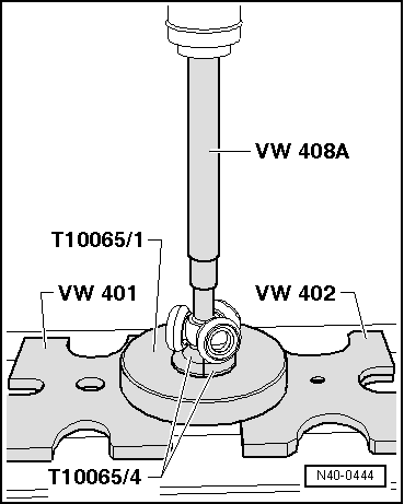
–  Press in balls one after the other from opposite sides, taking care to re-establish original position of hub relative to cage and joint body.
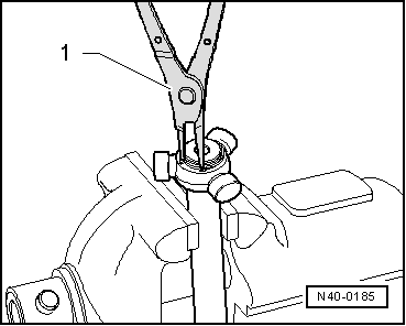
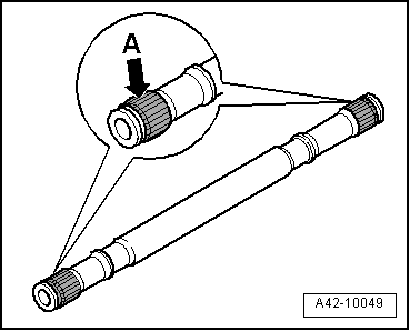
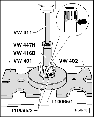
–  Fit new circlip in shaft.
–  Distribute remaining grease in boot.
  A40-0156

Rear suspension, drive shaft > < Servicing drive shaft with triple roller joint AAR 2600i (version with splines on inner joint) and AAR 3300i (version with inter