
A3 Mk2
|
| Grease | Outer joint | Inner joint |
| Total quantity | 140 g | 140 g |
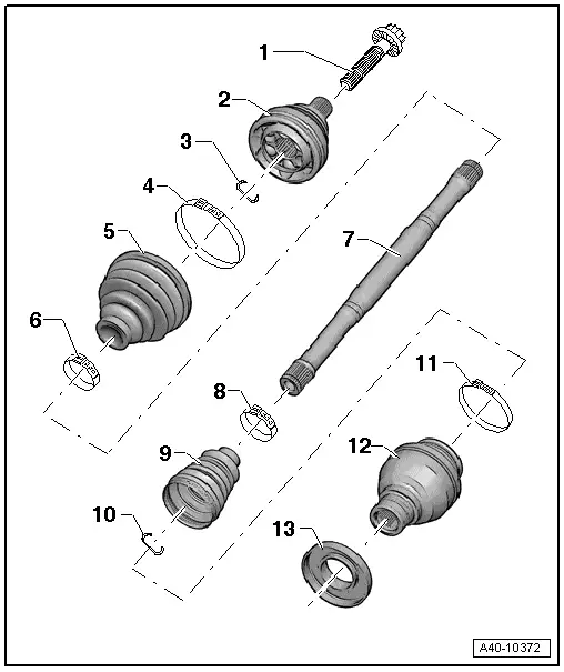
| 1 - | Bolt |
| q | Different versions possible. For correct version refer to → Electronic parts catalogue „ETKA“ |
| q | Always renew if removed |
| q | Hexagon bolt = 200 Nm + turn 180° further; loosening and tightening → Chapter |
| q | Twelve-point ribbed bolt = 70 Nm + turn 90° further; loosening and tightening → Chapter |
| q | Twelve-point bolt without ribbing = 200 Nm + turn 180° further; loosening and tightening → Chapter |
| q | Before securing, clean the threads in the CV joint using a thread tap. |
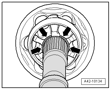
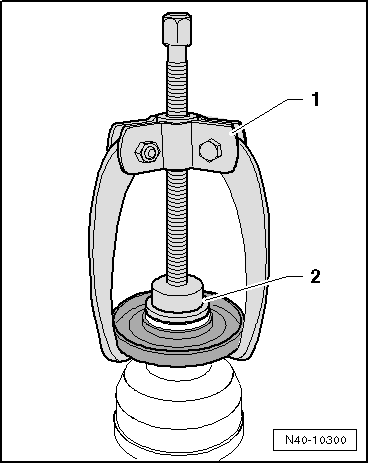
| 2 - | Outer constant velocity joint |
| q | Renew only as complete unit |
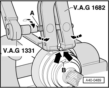
| q | Removing → Fig. |
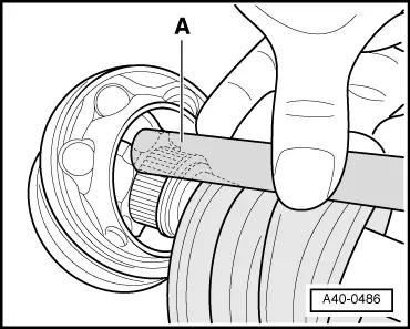
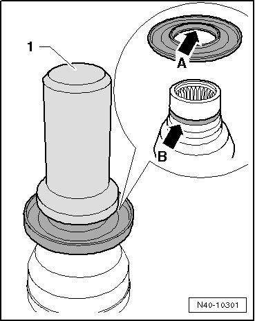
| q | Distribute grease filling through ball races → Anchor |
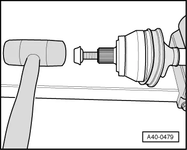
| q | Installing: drive onto shaft as far as stop using a plastic head hammer |
| q | Checking → Chapter |
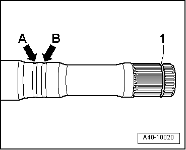
| 3 - | Circlip |
| q | Always renew if removed |
| q | Insert in groove on shaft |
| 4 - | Hose clip |
| q | Always renew if removed |
| q | Tightening → Fig. |
| 5 - | Boot |
| q | Check for splits and chafing |
| q | Material: Hytrel (polyelastomer) |
| 6 - | Hose clip |
| q | Always renew if removed |
| q | Tightening → Fig. |
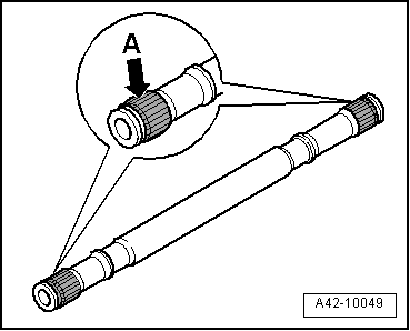
| 7 - | Drive shaft |
| 8 - | Hose clip |
| q | Always renew if removed |
| q | Tightening → Fig. |
| 9 - | Boot for sliding constant velocity joint |
| q | Material: Hytrel (polyelastomer) |
| q | Check for splits and chafing |
| 10 - | Circlip |
| q | Always renew if removed |
| q | Insert in groove on shaft |
| 11 - | Hose clip |
| q | Always renew if removed |
| q | Tightening → Fig. |
| 12 - | Sliding constant velocity joint |
| q | Renew only as complete unit |
| q | Removing → Fig. |
| q | Distribute grease filling through ball races → Anchor |
| q | Installing: drive onto shaft as far as stop using a plastic head hammer |
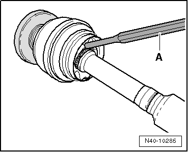
| 13 - | Protective cap |
| q | Detaching → Fig. |
| q | Driving on → Fig. |
|
|
|
|
|
|
|
|
|
|
|
|
 Note
Note
|
|
|
|
|
|