
A3 Mk2
| Removing and installing swivel joint |
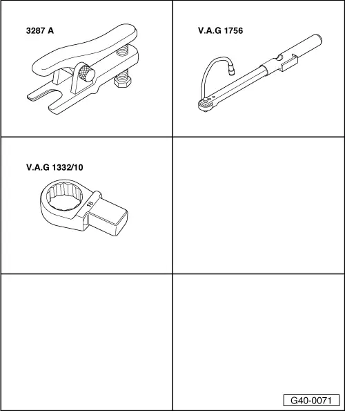
| Special tools and workshop equipment required |
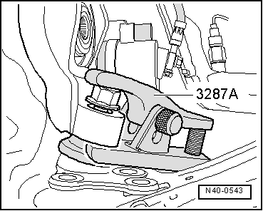
| t | Ball joint puller -3287 A- |
| t | Angle wrench -V.A.G 1756- |
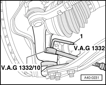
| t | Ring spanner insert -V.A.G 1332/10- |
|
 Note
Note
|
|
|
|
 WARNING
Note
|
|