audi Workshop Repair Guides

Audi Workshop Service and Repair Manuals

Servicing suspension strut > < Exploded view of suspension strut
Removing and installing suspension strut
Special tools and workshop equipment required
   
t  Angle wrench -V.A.G 1756-
  W00-0449
t  Torque wrench -V.A.G 1332-
  W00-0428
t  Spreader -3424-
  W00-0413
t  Ball joint puller -3287 A-
Removing
–  Loosen bolt securing drive shaft at wheel hub.
t  Loosen bolt securing drive shaft at wheel hub; procedure → Chapter „Loosening and tightening hexagon bolt securing drive shaft“.
t  Loosen bolt securing drive shaft at wheel hub; procedure → Chapter „Loosening and tightening twelve-point ribbed bolt securing drive shaft“.
t  Loosen bolt securing drive shaft at wheel hub; procedure → Chapter „Loosening and tightening twelve-point bolt (without ribbing) securing drive shaft“.
–  Remove wheel.
–  Detach brake caliper and secure to body with wire → Brake system; Repair group 46; Servicing front brakes.
–  Detach bracket for brake line and electrical wiring from wheel bearing housing.
–  Remove ABS speed sensor → Brake system; Repair group 46; Servicing front brakes.
  W00-0498
–  Unscrew top hexagon nut for coupling rod -arrow- from suspension strut.
–  Detach speed sensor wiring from suspension strut.
  N40-10004
–  Slacken off nut on track rod ball joint (but do not remove yet).
–  Press track rod ball joint out of wheel bearing housing using ball joint puller -3287A- (and then unscrew nut).
  N48-10011
–  On vehicles with vehicle level sender, unscrew nut -3-.
  A40-0534
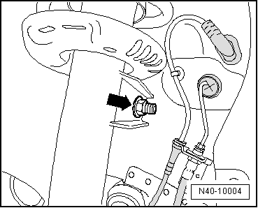
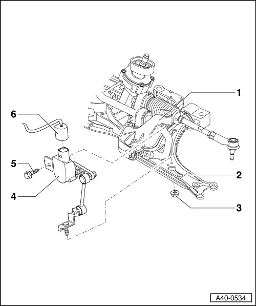
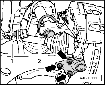
–  On vehicles with electronic damping control (Audi magnetic ride), unplug connector -2-.
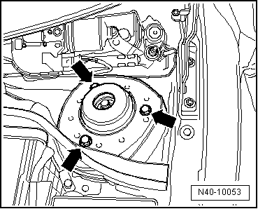
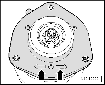
-Arrows- can be disregarded.
  Note
Use both hands to remove the connector: open the catch with one hand whilst pressing off the connector with the other; do not use any tools.
–  Unscrew nuts -arrows-.
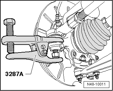
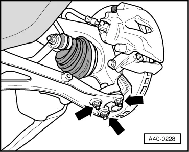
–  Detach wishbone from swivel joint and pull wheel bearing housing off drive shaft splines.
  Note
t  Do not let the drive shaft hang down under its own weight, as otherwise excessive bending could damage the inner CV joint.
t  Tie up drive shaft to body with wire.
–  Remove plenum chamber cover → Rep. gr.50.
  A40-10111
–  Unscrew hexagon bolts -arrows- for upper shock absorber mounting.
–  Take out suspension strut.
  N40-10053
–  Detach bolt connection between suspension strut and wheel bearing housing.
–  Insert spreader -3424- in slot in wheel bearing housing.
–  Turn ratchet handle through 90° and pull ratchet handle off spreader -3424-.
–  Pull suspension strut -1- out of wheel bearing housing -2-.
Installing
Installation is performed in reverse sequence; note the following:
Tightening torques → Chapter „Exploded view of wheel bearing housing and wheel bearing unit“
Tightening torques → Chapter „Exploded view of subframe, diagonal strut, swivel joint, anti-roll bar, wishbone, suspension bracket and vehicle level senders“
  A40-10140
–  Insert suspension strut; one of the two markings -arrows- must face in direction of travel.
  N40-10000
–  Tighten nuts -arrows-.
–  Tighten bolt securing drive shaft to wheel hub.
t  Tighten bolt securing drive shaft at wheel hub; procedure → Chapter „Loosening and tightening hexagon bolt securing drive shaft“.
t  Tighten bolt securing drive shaft at wheel hub; procedure → Chapter „Loosening and tightening twelve-point ribbed bolt securing drive shaft“.
t  Tighten bolt securing drive shaft at wheel hub; procedure → Chapter „Loosening and tightening twelve-point bolt (without ribbing) securing drive shaft“.
–  Install plenum chamber cover → Rep. gr.50.
–  On vehicles with electronic damping control (Audi magnetic ride), re-adapt reference position → Vehicle diagnostic tester.
–  On vehicles with vehicle level sender, carry out basic adjustment of headlights → Rep. gr.94.
–  Check and adjust wheel alignment as required, see chart → Anchor.
  A40-0228

Servicing suspension strut > < Exploded view of suspension strut