| Removing and installing rear left vehicle level sender -G76- and rear right vehicle level sender -G77- (on vehicle) |
| Special tools and workshop equipment required |
| t
| Torque wrench -V.A.G 1331- |
| Vehicles with electronic damping control (Audi magnetic ride) and/or gas discharge headlights have automatic headlight range control fitted as standard equipment → Rep. gr.94. |
| The electronic damping control (Audi magnetic ride) and the automatic headlight range control functions require information on the compression and rebound travel at the front and rear suspension. |
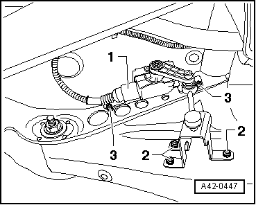
| For this purpose, the position of the left/right transverse link in relation to the body is transferred to the rear left vehicle level sender -G76- and the rear right vehicle level sender -G77- via a coupling rod. The senders then transmit electrical signals to the electronically controlled damping control unit -J250- and/or the gas discharge light control units (left/right) -J343/344-. |
| Servicing left/right gas discharge bulb control unit -J343/344- → Rep. gr.94 |
| On the front axle these signals are supplied by the front left vehicle level sender -G78- and front right vehicle level sender -G289- to the electronically controlled damping control unit -J250- and/or the gas discharge light control units (left/right) -J343/344-. |
| These signals are required for calculating the current attitude of the vehicle. |
| The automatic headlight range control reacts to changes in the suspension height (attitude of the vehicle). |
| The following situations may produce a change in the suspension height: |
| t
| Towing a trailer/caravan |
| t
| Different loads (vehicle unladen, partly laden or fully laden) |

Note | The basic headlight setting must always be checked and, on vehicles with electronic damping control (Audi magnetic ride), the reference position of the suspension must always be re-adapted in the following cases: |
| t
| If work has been performed on the vehicle level sender, |
| t
| If the lower transverse link has been removed and installed, |
|
|
|