audi Workshop Repair Guides

Audi Workshop Service and Repair Manuals

Renewing and adjusting hydraulic thrust piece > < Removing and installing rubber bush
Renewing sensor wiring
  Note
This repair is not possible at present.
Special tools and workshop equipment required
   
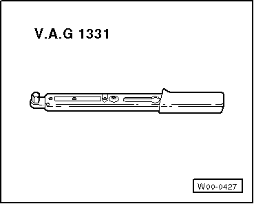
t  Torque wrench -V.A.G 1331-
  W00-0427
Removing
–  Remove steering box → Chapter.
–  Clean steering box in area of cover.
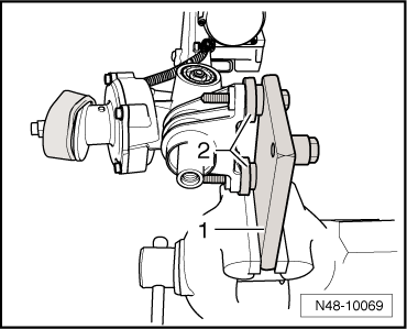
–  Clamp steering box in a vice as shown.
1 - Bracket VW 540/2
2 - Press tool 3253/6 (2x)
–  Unclip sensor wiring at steering box housing.
  N48-10069
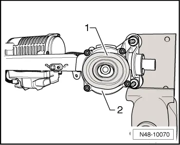
–  Remove seal -1- from cover -2-.
–  Detach cover -2-.
–  Carefully remove seal from steering box housing.
Make sure that sealant residue does not enter sensor or housing.
  N48-10070
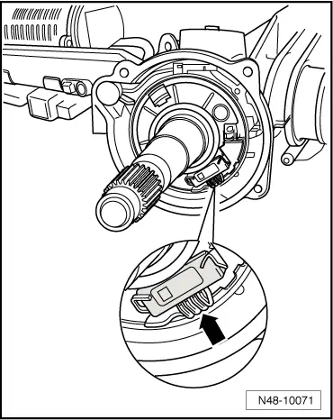
Avoid touching electrical contacts -arrow-.
–  Note general repair instructions → Chapter.
  N48-10071
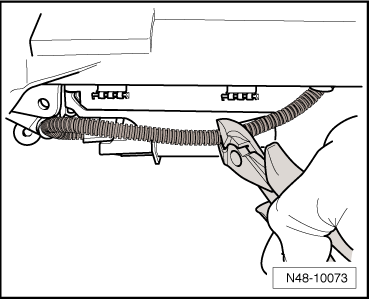
–  Cut off connector contact from wiring harness and store in a safe place.
It will be required for coding the new sensor wiring. The new sensor wiring is not fitted with a connector.
  Note
  N48-10073
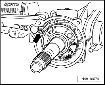
The sensor wiring in the steering box housing is fitted with a securing element -arrow- for the steering pinion coil spring. Make sure that the coil spring is not twisted when removing the sensor wiring.
  N48-10074
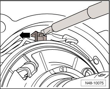
–  Now unplug sensor wiring connector at steering pinion.
To do this, press the connector contact out of the coil spring housing using a screwdriver (width of blade 3 mm) as shown in illustration.
–  Pull securing element out of steering box housing.
–  Pull sensor wiring out of steering box housing.
  N48-10075
Installing
–  Insert sensor wiring into steering box housing.
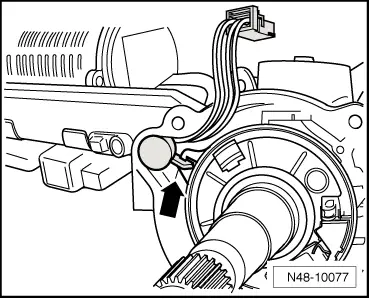
–  Lock coil spring with sensor wiring -arrow- to steering box housing.
–  Plug connector into coil spring housing.
The connector is coded and can only be fitted in one position.
  N48-10077
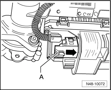
–  Unplug old connector from control unit.
–  To unplug connector, press button -a- in direction of arrow.
–  Insert wires of new sensor wiring into new connector.
–  Take over designations on old connector for the coding procedure.
  N48-10072
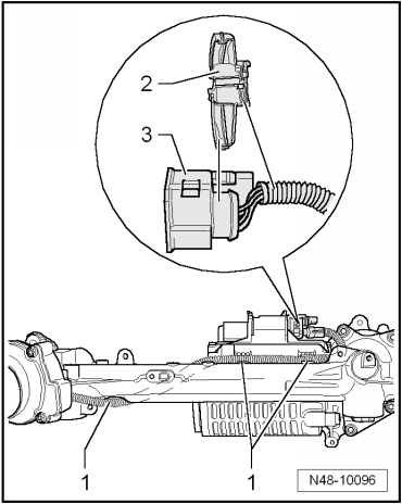
–  Clip adapter -2- to connector housing -3-.
–  Clip sensor wiring to steering box housing -1-.
Note routing of wires.
–  Plug connector onto control unit.
  N48-10096
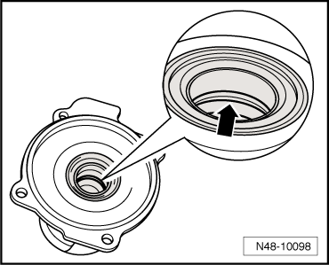
–  Apply only a very thin coat of grease -G 052 168 A1- when lubricating the seal -arrow- in the cover.
–  Install cover with new seal.
Remaining installation steps are carried out in reverse sequence.
Tightening torques → Chapter „Exploded view of electromechanical steering box (generation 1)“
–  Check wheel alignment → Chapter
Perform a basic setting for the steering angle sender -G85- using vehicle diagnostic, testing and information system -VAS 5051B- after installing.
  N48-10098

Renewing and adjusting hydraulic thrust piece > < Removing and installing rubber bush