
A4 Cabriolet Mk2
| ABS/ESP components: exploded view |
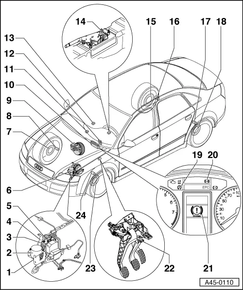
| 1 - | Carrier for hydraulic control units |
| q | Removing and installing → Chapter |
| 2 - | Vacuum pump for brake servo |
| q | Only on petrol engines with automatic gearbox |
| 3 - | ABS control unit -J104- |
| q | The ABS hydraulic unit -N55- and the ABS control unit -J104- together make up the hydraulic control unit. |
| q | Removing and installing → Chapter |
| 4 - | ABS hydraulic unit -N55- with ABS control unit -J104- |
| q | The ABS hydraulic unit -N55- and the ABS control unit -J104- together make up the hydraulic control unit. |
| q | Removing and installing → Chapter |
| 5 - | Brake pressure sender 1 -G201- |
| q | Screws onto hydraulic unit |
| 6 - | ABS hydraulic unit -N55- with ABS control unit -J104- |
| 7 - | Rotor for speed sensor (front right) |
| q | Checking / removing and installing → Anchor |
| 8 - | Front right speed sensor -G45- |
| q | Removing and installing → Chapter |
| 9 - | Brake fluid level warning contact -F34- |
| 10 - | Dash panel insert |
| 11 - | Traction control system switch -E132- |
| q | Fitting location: on centre console |
| 12 - | Steering angle sender -G85- |
| q | Fitting location: incorporated in return ring with slip ring on steering column → Rep. Gr.69 |
| q | Performing zero compensation → VAS 5051 vehicle diagnostic, testing and information system |
| 13 - | Lateral acceleration sender -G200- and yaw rate sender -G202- |
| q | Fitting location: below radio |
| q | On vehicles with Hill Holder function, zero compensation must be performed for ESP sensor unit -G419- |
| q | Removing and installing → Chapter |
| 14 - | Handbrake warning switch -F9- |
| q | Fitting location: on handbrake lever unit |
| 15 - | Rotor for speed sensor (rear right) |
| q | Checking front-wheel drive → Anchor |
| q | Checking four-wheel drive → Anchor |
| 16 - | Rear right speed sensor -G44- |
| q | Removing and installing (vehicles with front-wheel drive) → Chapter |
| q | Removing and installing (vehicles with four-wheel drive) → Chapter |
| 17 - | Rear left speed sensor -G46- |
| q | Removing and installing (vehicles with front-wheel drive) → Chapter |
| q | Removing and installing (vehicles with four-wheel drive) → Chapter |
| 18 - | Rotor for speed sensor (rear left) |
| q | Checking front-wheel drive → Anchor |
| q | Checking four-wheel drive → Anchor |
| 19 - | Traction control system warning lamp -K86- |
| q | Location: on dash panel insert |
| q | See Owner's Manual for further information |
| 20 - | ABS warning lamp -K47- |
| q | Location: on dash panel insert |
| q | See Owner's Manual for further information |
| 21 - | Brake system warning lamp -K118-; “brake warning” symbol |
| q | Fitting location: in driver information system/ dash panel insert |
| q | See Owner's Manual for further information |
| 22 - | Brake light switch -F- |
| q | Removing and installing brake light switch → Chapter. |
| q | Adjusting → Chapter |
| 23 - | Rotor for speed sensor (front left) |
| q | Checking / removing and installing → Anchor |
| 24 - | Front left speed sensor -G47- |
| q | Removing and installing → Chapter |