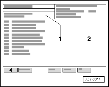
| Indicated on display of vehicle diagnostic, testing and information system -VAS 5051A-: |
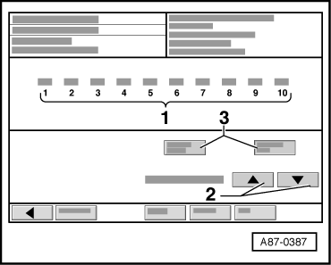
| The following control motors are now actuated and their current feedback value is indicated in display zone “1”. At present the control motors are arranged as follows: |
| t
| 1. position: Left temperature flap control motor -V158- |
| t
| 2. position: Right temperature flap control motor -V159- |
| t
| 3. position: Defroster flap control motor -V107- |
| t
| 4. position: Central flap control motor -V70- |
| t
| 5. position: Air flow flap control motor -V71- (left-hand drive vehicles only; “255” is displayed for right-hand drive vehicles with no control motor, as there is no control motor connected) |
| t
| 6. position: Air recirculation flap control motor -V113- |
| The end positions of the control motors (resistance values in stop position) are stored in the operating and display unit, Climatronic control unit -J255- (resistance value of potentiometers in control motors) and used for further control action. |
| Once the control motors have reached both end stops, they are moved again from one stop to the other. During this process, the adjustment time is measured and stored in the operating and display unit, Climatronic control unit -J255- for use in the event of emergency operation. |
|
|
|
 Note
Note